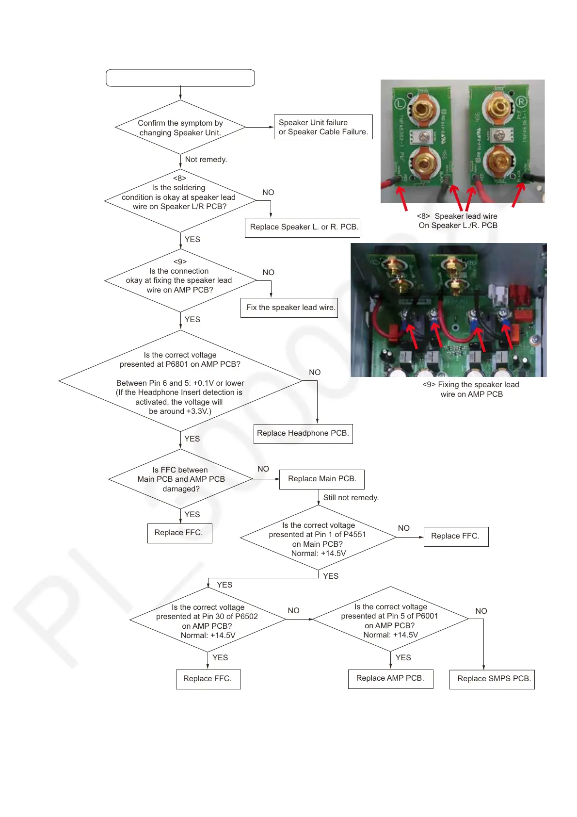
7.12. No Sound from Speaker Unit
No Sound from Speaker Unit.
Confirm the symptom by
changing Speaker Unit.
Not remedy.
Speaker Unit failure
or Speaker Cable Failure.
<8>
Is the soldering
condition is okay at speaker lead
wire on Speaker L/R PCB?
YES
Replace Speaker L. or R. PCB.
Remedy.
<8> Speaker lead wire
On Speaker L./R. PCB
NO
<9>
Is the connection
okay at fixing the speaker lead
wire on AMP PCB?
<9> Fixing the speaker lead
wire on AMP PCB
Fix the speaker lead wire.
NO
YES
Is the correct voltage
presented at P6801 on AMP PCB?
Between Pin 6 and 5: +0.1V or lower
(If the Headphone Insert detection is
activated, the voltage will
be around +3.3V.)
NO
Replace Headphone PCB.
Replace Main PCB.
Is FFC between
Main PCB and AMP PCB
damaged?
YES
Replace FFC.
NO
YES
Still not remedy.
YES
Replace FFC.
Is the correct voltage
presented at Pin 1 of P4551
on Main PCB?
Normal: +14.5V
Replace AMP PCB.
Replace SMPS PCB.
Is the correct voltage
presented at Pin 30 of P6502
on AMP PCB?
Normal: +14.5V
NO
Replace FFC.
NO
YES
Is the correct voltage
presented at Pin 5 of P6001
on AMP PCB?
Normal: +14.5V
YES
YES
NO