48
9 Service Position
Note: For description of the disassembly procedures, see the Section 8.
9.1. Checking and Repairing of SMPS P.C.B., AMP P.C.B., Main P.C.B., Con-
trol P.C.B., Digital P.C.B. and REC Out P.C.B.
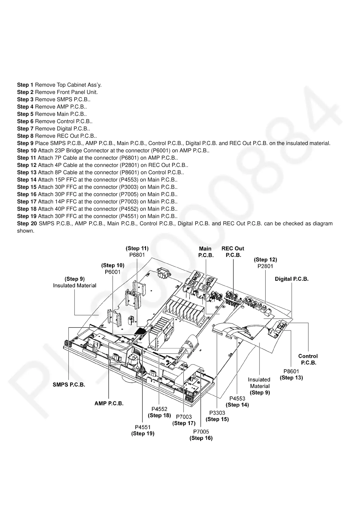
Step 1 Remove Top Cabinet Ass’y.
Step 2 Remove Front Panel Unit.
Step 3 Remove SMPS P.C.B..
Step 4 Remove AMP P.C.B..
Step 5 Remove Main P.C.B..
Step 6 Remove Control P.C.B..
Step 7 Remove Digital P.C.B..
Step 8 Remove REC Out P.C.B..
Step 9 Place SMPS P.C.B., AMP P.C.B., Main P.C.B., Control P.C.B., Digital P.C.B. and REC Out P.C.B. on the insulated material.
Step 10 Attach 23P Bridge Connector at the connector (P6001) on AMP P.C.B..
Step 11 Attach 7P Cable at the connector (P6801) on AMP P.C.B..
Step 12 Attach 4P Cable at the connector (P2801) on REC Out P.C.B..
Step 13 Attach 8P Cable at the connector (P8601) on Control P.C.B..
Step 14 Attach 15P FFC at the connector (P4553) on Main P.C.B..
Step 15 Attach 30P FFC at the connector (P3003) on Main P.C.B..
Step 16 Attach 30P FFC at the connector (P7005) on Main P.C.B..
Step 17 Attach 14P FFC at the connector (P7003) on Main P.C.B..
Step 18 Attach 40P FFC at the connector (P4552) on Main P.C.B..
Step 19 Attach 30P FFC at the connector (P4551) on Main P.C.B..
Step 20 SMPS P.C.B., AMP P.C.B., Main P.C.B., Control P.C.B., Digital P.C.B. and REC Out P.C.B. can be checked as diagram
shown.