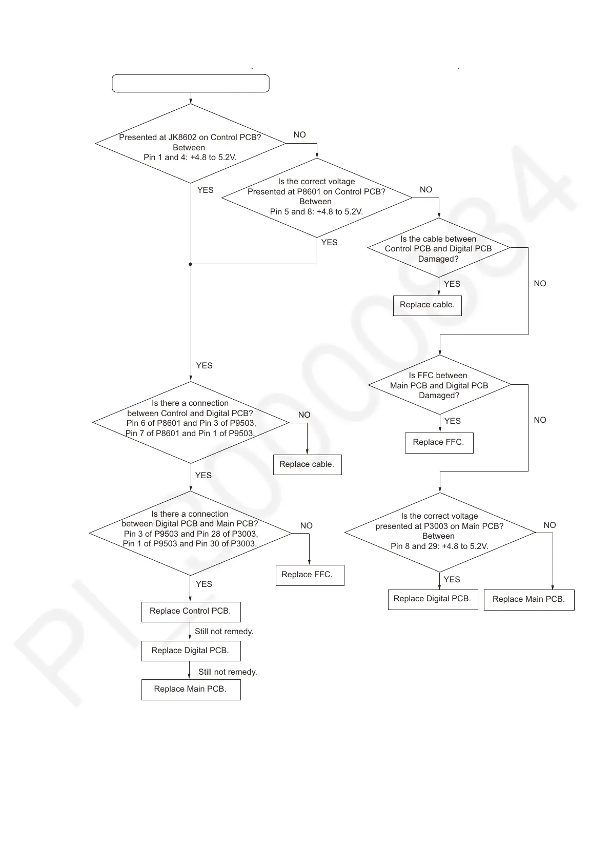
7.10. No SUB Function (Firmware UPDATE terminal)
No SUB Function.
YES
( )
Is the correct voltage
Presented at JK8602 on Control PCB?
Between
Pin 1 and 4: +4.8 to 5.2V.
NO
NO
Is there a connection
between Control and Digital PCB?
Pin 6 of P8601 and Pin 3 of P9503,
Pin 7 of P8601 and Pin 1 of P9503.
Is the correct voltage
Presented at P8601 on Control PCB?
Between
Pin 5 and 8: +4.8 to 5.2V.
Is the cable between
Control PCB and Digital PCB
Damaged?
YES
YES
YES
Replace cable.
NO
Is FFC between
Main PCB and Digital PCB
Damaged?
YES
Replace FFC.
Is the correct voltage
presented at P3003 on Main PCB?
Between
Pin 8 and 29: +4.8 to 5.2V.
NO
Replace Main PCB.
NO
YES
Replace Digital PCB.
NO
Replace cable.
YES
Is there a connection
between Digital PCB and Main PCB?
Pin 3 of P9503 and Pin 28 of P3003,
Pin 1 of P9503 and Pin 30 of P3003.
NO
Replace FFC.
Replace Control PCB.
Replace Digital PCB.
Replace Main PCB.
Still not remedy.
Still not remedy.
YES