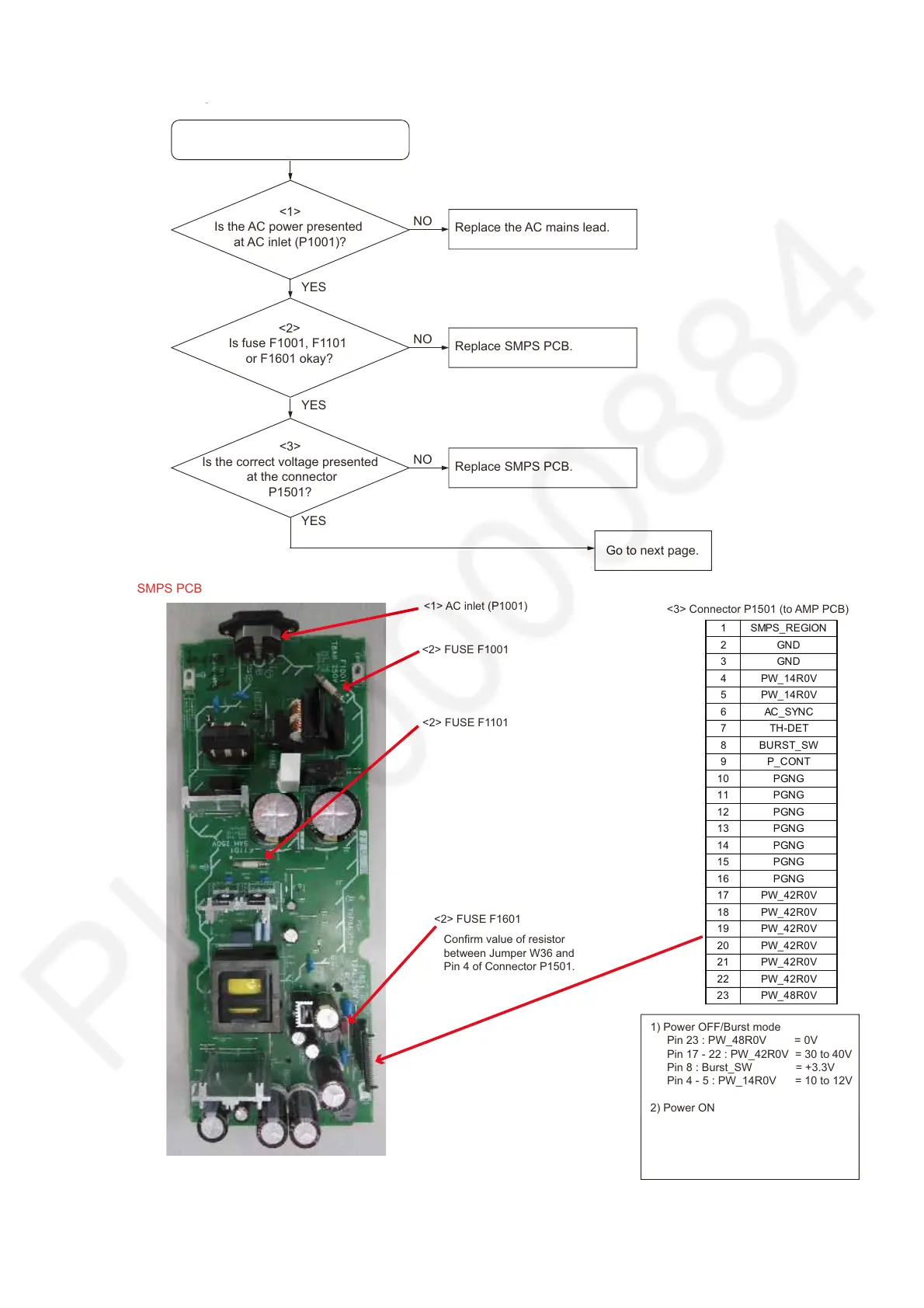
7.2. No power
Replace the AC mains lead.
NO
<1>
Is the AC power presented
at AC inlet (P1001)?
Replace SMPS PCB.
NO
<2>
Is fuse F1001, F1101
or F1601 okay?
Replace SMPS PCB.
NO
<3>
Is the correct voltage presented
at the connector
P1501?
No power
SMPS PCB
YES
YES
p
<1> AC inlet (P1001)
<2> FUSE F1001
<3> Connector P1501 (to AMP PCB)
YES
Go to next page.
1) Power OFF/Burst mode
Pin 23 : PW_48R0V = 0V
Pin 17 - 22 : PW_42R0V = 30 to40V
Pin 8 : Burst_SW = +3.3V
Pin 4 - 5 : PW_14R0V = 10 to 12V
2) Power ON
Pin 23 : PW_48R0V = 48 to 52V
Pin 17 - 22 : PW_42R0V = 42 to 47V
Pin 8 : Burst_SW = 0V
Pin 4 - 5 : PW_14R0V = 14 to 15V
<2> FUSE F1101
<2> FUSE F1601