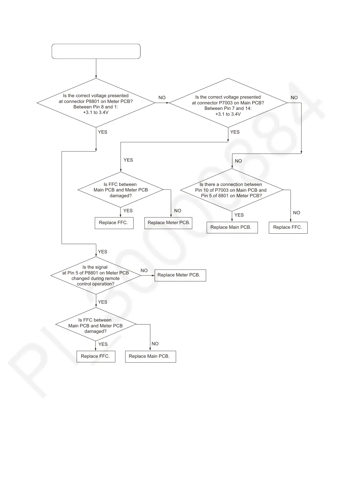
7.7. No Remote Control Operation
No Remote Control Operation.
YES
Is the correct voltage presented
at connector P8801 on Meter PCB?
Between Pin 8 and 1:
+3.1 to 3.4V
Is the signal
at Pin 5 of P8801 on Meter PCB
changed during remote
control operation?
Replace Main PCB.
Is there a connection between
Pin 10 of P7003 on Main PCB and
Pin 5 of 8801 on Meter PCB?
YES
Replace FFC.
NO
NO
Replace Meter PCB.
Is FFC between
Main PCB and Meter PCB
damaged?
YES
Replace FFC.
NO
YES
YES
NO
Is the correct voltage presented
at connector P7003 on Main PCB?
Between Pin 7 and 14:
+3.1 to 3.4V
NO
YES
Replace Meter PCB.
YES
Replace Main PCB.
Is FFC between
Main PCB and Meter PCB
damaged?
YES
Replace FFC.
NO
NO