EasyManua.ls Logo

Technics SU-G700E User Manual

Technics SU-G700E
59 pages
To Next Page IconTo Next Page
Page #1 background imageLoading...
Page #1 background image
© Panasonic Corporation 2017. All rights reserved.
Unauthorized copying and distribution is a violation
of law.
PSG1704003CE
A6
Stereo Integrated Amplifier
Model No. SU-G700E
SU-G700PP
Product Color: (S)...Silver Type
TABLE OF CONTENTS
PAGE PAGE
1 Safety Precautions----------------------------------------------- 3
1.1. General Guidelines---------------------------------------- 3
1.2. Before Repair and Adjustment ------------------------- 4
1.3. Protection Circuitry---------------------------------------- 5
1.4. Safety Parts Information --------------------------------- 5
2 Warning-------------------------------------------------------------- 6
2.1. Prevention of Electrostatic Discharge (ESD)
to Electrostatically Sensitive (ES) Devices---------- 6
2.2. General description about Lead Free Solder
(PbF)---------------------------------------------------------- 6
2.3. Grounding for electrostatic breakdown
prevention --------------------------------------------------- 7
3 Service Navigation----------------------------------------------- 8
3.1. Service Information --------------------------------------- 8
4 Specifications ----------------------------------------------------- 9
5 Location of Controls and Components ------------------10
5.1. Remote Control Key Button Operation--------------10
5.2. Main Unit Key Button Operation----------------------11
6 Service Mode -----------------------------------------------------12
6.1. Doctor Mode -----------------------------------------------12
6.2. Error Code Table ----------------------------------------- 15
7 Troubleshooting Guide --------------------------------------- 16
7.1. Check the problem is reproduced-------------------- 16
7.2. No power--------------------------------------------------- 17
7.3. Automatically shutdown during operation---------- 20
7.4. No Display ------------------------------------------------- 21
7.5. Power Indicator - Not Light ---------------------------- 22
7.6. Meter Illumination - No Light -------------------------- 23
7.7. No Remote Control Operation------------------------ 24
7.8. Can not control Volume +/- ---------------------------- 25
7.9. Can not control Input Selection----------------------- 26
7.10. No SUB Function (Firmware UPDATE
terminal) ---------------------------------------------------- 27
7.11. No Sound input from PC (USB-B), COAX IN
or OPT IN -------------------------------------------------- 28
7.12. No Sound from Speaker Unit ------------------------- 29
7.13. No Sound from Headphone --------------------------- 30
7.14. No Sound from LINE OUT Terminal----------------- 31
7.15. No Meter Operation ------------------------------------- 32
7.16. No System Control (Control Terminal)-------------- 33

Table of Contents

Question and Answer IconNeed help?

Do you have a question about the Technics SU-G700E and is the answer not in the manual?

Technics SU-G700E Specifications

General IconGeneral
TypeIntegrated Amplifier
Input Impedance47 kΩ
Input Sensitivity200 mV
USB DACYes
Output Power (8 Ohms)70 W
Output Power (4 Ohms)140 W
Total Harmonic Distortion (THD)0.01%
Signal-to-Noise Ratio100 dB
Digital InputsOptical x 2, Coaxial x 1
Analog Inputs4 x RCA
Analog OutputsLine x 1
DSD PlaybackYes
PCM PlaybackYes (up to 384kHz / 32bit)

Summary

1 Safety Precautions

1.2 Before Repair and Adjustment

Discharging capacitors and pre-repair checks.

2 Warning

2.1 Prevention of Electrostatic Discharge (ESD)

Techniques to reduce component damage from static electricity.

6 Service Mode

6.1 Doctor Mode

Procedure to enter and navigate the special service mode.

7 Troubleshooting Guide

7.2 No power

Troubleshooting steps for the unit not turning on.

7.3 Automatically shutdown during operation

Diagnosing issues causing unexpected power-off during use.

7.4 No Display

Steps to resolve when the unit's screen shows no output.

7.7 No Remote Control Operation

Steps to take when the remote control is unresponsive.

7.11 No Sound input from PC (USB-B), COAX IN or OPT IN

Diagnosing no audio from digital input sources like PC, COAX, or OPT.

7.12 No Sound from Speaker Unit

Troubleshooting steps when no sound comes from speakers.

7.13 No Sound from Headphone

Diagnosing headphone audio output issues.

7.14 No Sound from LINE OUT Terminal

Troubleshooting no audio output from the LINE OUT terminal.

7.17 No Audio Output from PRE OUT terminal

Diagnosing no audio from the PRE OUT terminal.

8 Disassembly and Assembly Instructions

8.5 Disassembly of SMPS P.C.В.

Procedure for removing the Switched-Mode Power Supply PCB.

8.6 Disassembly of AMP P.C.В.

Steps for removing the Amplifier Printed Circuit Board.

8.11 Disassembly of Main P.C.B.

Procedure for removing the main printed circuit board.

9 Service Position

10 Measurement and Adjustment

10.1 Adjustment of the Peak Power Meter

Procedure for adjusting the peak power meter after component replacement.
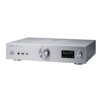
Related product manuals