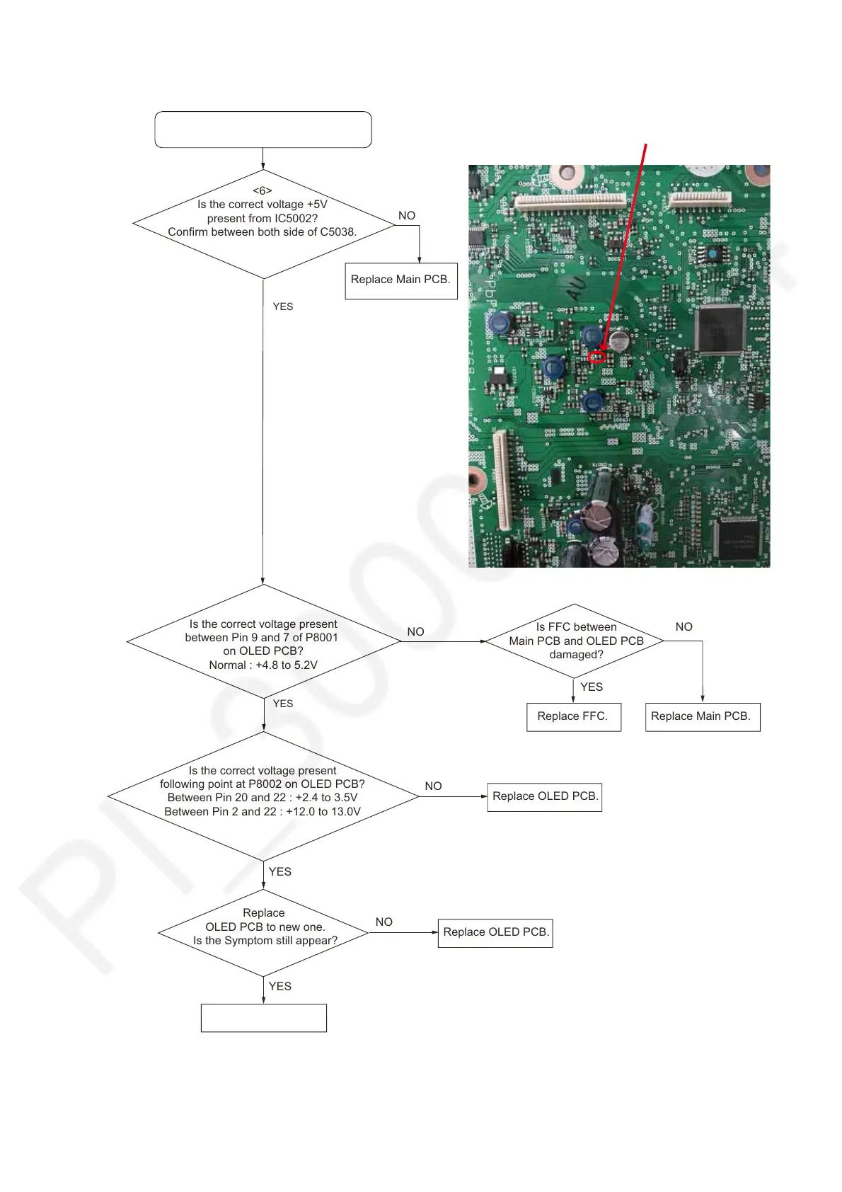
7.4. No Display
Is the correct voltage present
between Pin 9 and 7 of P8001
on OLED PCB?
Normal : +4.8 to 5.2V
No Display.
YES
Replace Main PCB.
NO
<6>
Is the correct voltage +5V
present from IC5002?
Confirm between both side of C5038.
YES
NO
Main PCB
<6>
+4.8 to 5.2V :
between both side of C5038
Is FFC between
Main PCB and OLED PCB
damaged?
YES
NO
Replace Main PCB.
Replace FFC.
Is the correct voltage present
following point at P8002 on OLED PCB?
Between Pin 20 and 22 : +2.4 to 3.5V
Between Pin 2 and 22 : +12.0 to 13.0V
Replace OLED PCB.
NO
Replace
OLED PCB to new one.
Is the Symptom still appear?
YES
Replace Main PCB.
YES
Replace OLED PCB.
NO