5
98-05141 R2www.teejet.com
CONFIGURATIONS
The following diagrams are refl ective of typical Matrix confi gurations. Due to the variety of possible
confi gurations, these should be used for reference purposes only.
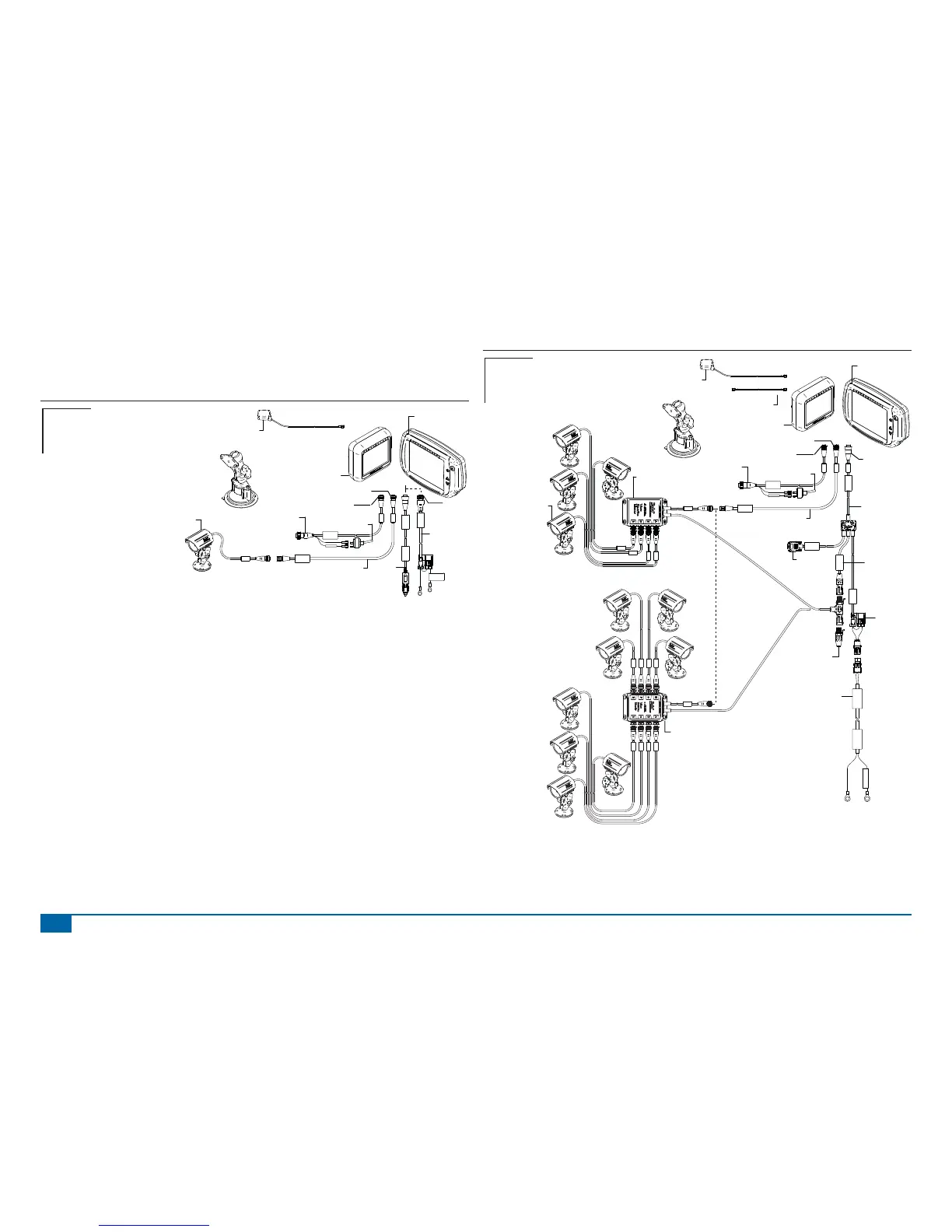
Figure 1-14: Matrix w/RealView Camera
16-00022: Camera
Connectto
+12v On ly
Power Cable
45-05645
Power
Cable, 12V
45-05775
10' Power
Cable, Battery
CAUTION CONN.
TO +12V ONLY
POWER CABLE
45-05775
DC: XXXX
8 Pos.
4 Pos.
8 Pos.
Speed Cable
Camera
45-05617: 20'
45-05618: 60'
Camera Extension Cable
45-05615 4 Pos.
45-05765 8 Pos.
Speed/Sense Cable
5 Pos.
+12V
32-50008
Switch
78-50155
GPS Ant.
Matrix 570G
75-30055
75-30056 w/ClearPath
Kit, RAM Mount w/Suction Cup
90-02349 (Matrix 570G)
90-02700 (Matrix 840G)
Matrix 840G
75-30070
75-30071 w/ClearPath
Matrix
FieldPilot
BoomPilot
Optional Accessory
Speed Out / Sense In Cable
The Speed Out / Sense In Cable assists the Matrix with two additional connections that::
►Send a radar speed signal to an external device
►Allow the user to operate the area applied function of the Matrix in series with a remote master
connection or existing apply on/off toggle in a single swath manner. However if the previous connections
are not available the supplied toggle switch allows area applied functionality without the need to connect
to a functional application implement.
Connecting to different consoles requires different adapters and calibrations.
• If connecting to TeeJet consoles use speed adapter 45-20042
◄enter calibration # 914 (#1000 in Europe) for 8xx series in RAD mode,
◄enter calibration # 9140 (#10000 in Europe) for below LH 70 Series, LH 85, 500 series, 5000,
6000, IC 24 and IC 34
• If connecting to Mid-Tech consoles no adapter is required,
◄enter calibration # 1000
• If connecting to Raven consoles use speed adapter 45-05508 (do not connect the 12v red wire
from 45-05508)
◄enter calibration # 730 in SP 2
If sensing boom shut-off for applied mapping from an existing console, attach the green wire to the valve
side of the master switch on the console. The red wire is not used.
Figure 1-15: Matrix w/8 Channel or 4 Channel VSM & Multiple RealView Cameras
POWER IN
CAN
RS-232
Power/DATA
45-05626
45-05626
Pwr/CAN/Data
Cable
(included with
FieldPilot and
BoomPilot kits)
3A Fuse
8 Pos.
RS-232
TJ CAN
(Terminated)
CAUTION: CONNECT
TO 12V ONLY
Power Cable
401-0016
DC: xx/xx
WARNING CONNECT
DIRECTLY TO BAT.
401-0016
Battery Adapter
45-08101
CAN Terminator
16-00022
RealView Camera
78-08067
Module, 4CH
Video CAN
78-08068
Video Selector
Module,
8CH Video CAN
to Optional RXA GPS Antenna
45-05678
Cable, SMA-M X SMA-M
4 Pos.
8 Pos.
Speed Cable
Camera
45-05617: 20'
45-05618: 60'
Camera Extension Cable
45-05615 4 Pos.
45-05765 8 Pos.
Speed/Sense Cable
5 Pos.
+12V
32-50008
Switch
78-50155
GPS Ant.
Matrix 570G
75-30055
75-30056 w/ClearPath
Kit, RAM Mount w/Suction Cup
90-02349 (Matrix 570G)
90-02700 (Matrix 840G)
Matrix 840G
75-30070
75-30071 w/ClearPath
Matrix
FieldPilot
BoomPilot
Optional Accessory