What the Controls Do-222 DSO Operators
Table
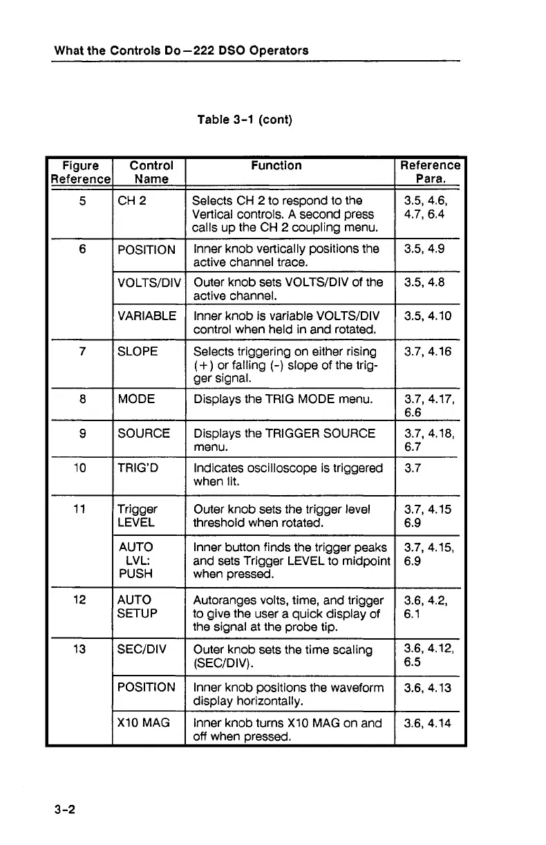
3-1
(cont)
Figure
leference
Control
Name
Function
Selects CH 2 to respond to the
Vertical controls. A second press
calls up the CH 2 coupling menu.
Reference
Para.
3.5, 4.6,
4.7, 6.4
VOLTSIDIV Outer knob sets VOLTSIDIV of the
I
active channel.
POSITION
VARIABLE Inner knob is variable VOLTSIDIV
control when held in and rotated.
SLOPE
Selects triggering on either rising
(+)
or falling
(-)
slope of the trig-
ger signal.
MODE Displays the
TRIG MODE menu.
menu.
when lit.
lnner knob vertically positions the
active channel trace.
3.5, 4.9
AUTO
LV
L:
PUSH
AUTO
SETUP
Trigger
LEVEL
lnner button finds the trigger peaks
and sets Trigger LEVEL to midpoint
when pressed.
Autoranges volts, time, and trigger
to give the user a quick display of
the signal
at
the probe tip.
Outer knob sets the trigger level
3.7, 4.15
threshold when rotated.
1
6.9
SEC'DIV
I
Outer knob sets the time scaling
3.6, 4.12,
(SECIDIV).
1
6.5
POSITION lnner knob positions the waveform 3.6, 4.13
I
display horizontally.
X10MAG
I
Inner knob turns XI0 MAG on and 3.6, 4.14
off when Dressed.