Operating Instructions—434
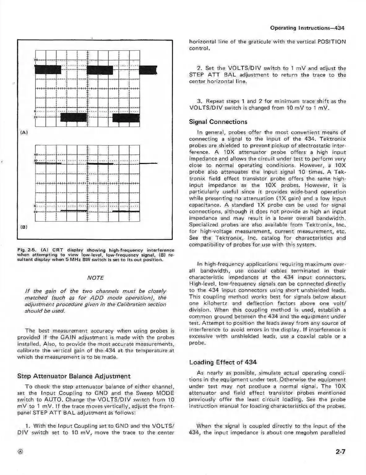
Fig. 2-5. (A ) C R T display sho w ing h igh -frequen cy interfere nce
when a tte m ptin g to view low -level, lo w -freq u ency signal, (B) re
sulta nt display w hen 5 M H z BW sw itch is set to its o u t p o sitio n.
NOTE
I f the gain o f the tw o channels m ust be closely
matched (such as fo r A D D mode operation), the
adjustm ent procedure given in the C alibration section
should be used.
The best measurement accuracy when using probes is
provided if the G AIN adjustm ent is made w ith the probes
installed. Also, to provide the most accurate measurements,
calibrate the vertical gain of the 434 at the temperature at
which the measurement is to be made.
Step A ttenuator Balance Adjustm ent
To check the step attenuator balance of either channel,
set the Input Coupling to GND and the Sweep MODE
switch to A U TO . Change the V O L T S /D IV switch from 10
m V to 1 m V. If the trace moves vertically, adjust the front-
panel STEP AT T B A L adjustm ent as follow s:
1. W ith the Inpu t Coupling set to GND and the VO LTS /
D IV switch set to 10 m V , move the trace to the center
horizontal line of the graticule with the vertical POSITION
control.
2. Set the V O LT S /D IV switch to 1 m V and adjust the
STEP A TT B A L adjustm ent to return the trace to the
center horizontal line.
3. Repeat steps 1 and 2 fo r m inim um trace shift as the
V O L T S /D IV switch is changed from 10 m V to 1 mV.
Signal Connections
In general, probes offer the most convenient means of
connecting a signal to the inpu t o f the 434. T e ktron ix
probes are shielded to prevent pickup of electrostatic inter
ference. A 10X attenuator probe offers a high input
impedance and allows the c ircuit under test to perform very
close to normal operating conditions. However, a 10X
probe also attenuates the inpu t signal 10 times. A Tek
tro n ix field effect transistor probe offers the same high-
input impedance as the 10X probes. However, it is
particularly useful since it provides wide band operation
while presenting no attenuation (IX gain) and a low input
capacitance. A standard IX probe can be used fo r signal
connections, although it does not provide as high an input
impedance and may result in a lower overall bandwidth.
Specialized probes are also available from T ek tro n ix, Inc.
fo r high-voltage measurement, current measurement, etc.
See the T ektro nix, Inc. catalog for characteristics and
com patibility o f probes for use w ith this system.
In high-frequency applications requiring maxim um over
all bandwidth, use coaxial cables terminated in their
characteristic impedances at the 434 input connectors.
High-level, low-frequency signals can be connected directly
to the 434 inp ut connectors using short unshielded leads.
This coupling method works best fo r signals below about
one kilohertz and deflection factors above one v o lt/
division. When this coupling method is used, establish a
comm on ground between the 434 and the equipm ent under
test. A tte m pt to position the leads away from any source of
interference to avoid errors in the display. If interference is
excessive w ith unshielded leads, use a coaxial cable or a
probe.
Loading Effect of 434
As nearly as possible, simulate actual operating condi
tions in the equipm ent under test. Otherwise the equipm ent
under test may not produce a normal signal. The 10X
attenuator and field effect transistor probes mentioned
previously offer the least circu it loading. See the probe
instruction manual fo r loading characteristics of the probes.
When the signal is coupled directly to the inp ut of the
434, the inpu t impedance is about one megohm paralleled
<S>
2-7