Specification—434
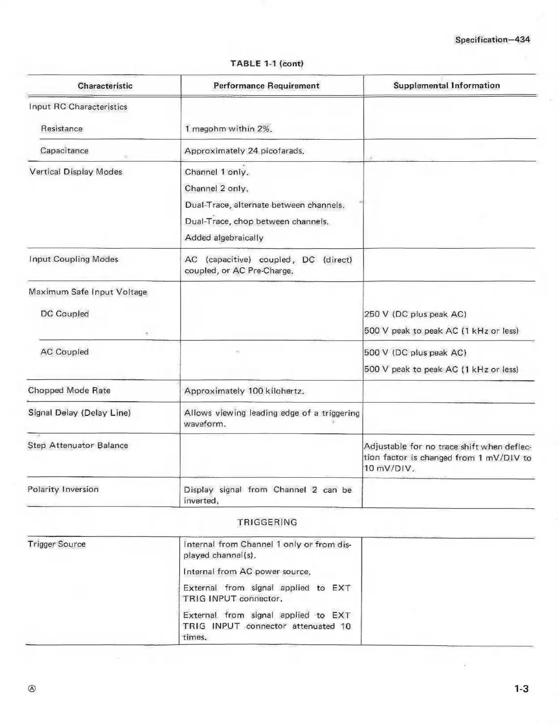
TABLE 1-1 (cont)
Characteristic
Performance Requirement Supplemental Inform ation
Input RC Characteristics
Resistance
1 megohm w ithin 2%.
Capacitance Approxim ately 24 picofarads.
Vertical Display Modes
Channel 1 only.
Channel 2 only.
Dual-Trace, alternate between channels.
Dual-Trace, chop between channels.
Added algebraically
Input Coupling Modes
AC (capacitive) coupled, DC (direct)
coupled, or AC Pre-Charge.
Maximum Safe Input Voltage
DC Coupled
250 V (DC plus peak AC)
500 V peak to peak AC (1 kHz or less)
AC Coupled
500 V (DC plus peak AC)
500 V peak to peak AC (1 kHz or less)
Chopped Mode Rate
Approximately 100 kilohertz.
Signal Delay (Delay Line)
Allows viewing leading edge o f a triggering
waveform.
Step Attenuator Balance
Adjustable fo r no trace shift when deflec
tion factor is changed from 1 m V/D IV to
10 m V /D IV.
Polarity Inversion
Display signal from Channel 2 can be
inverted.
TRIGGERING
Trigger Source
Internal from Channel 1 only or from dis
played channel(s).
Internal from AC power source.
External from signal applied to EXT
TR IG INPUT connector.
External from signal applied to EXT
TRIG INPUT connector attenuated 10
times.
1-3