Calibration—434
b. CHECK—Test oscilloscope display for 40 m icro
second time period between current peaks.
c. ADJUST—Current Sense adjustment R1074 (see Fig.
5-3) fo r 40 microseconds, ±one microsecond time period
between current peaks.
d. Disconnect all test equipment and re-install tbe
Power Supply compartment shields.
e. INTERA CTIO N —May affect the operation of all
circuits w ithin the 432.
4. Adjust High-Voltage Power Supply
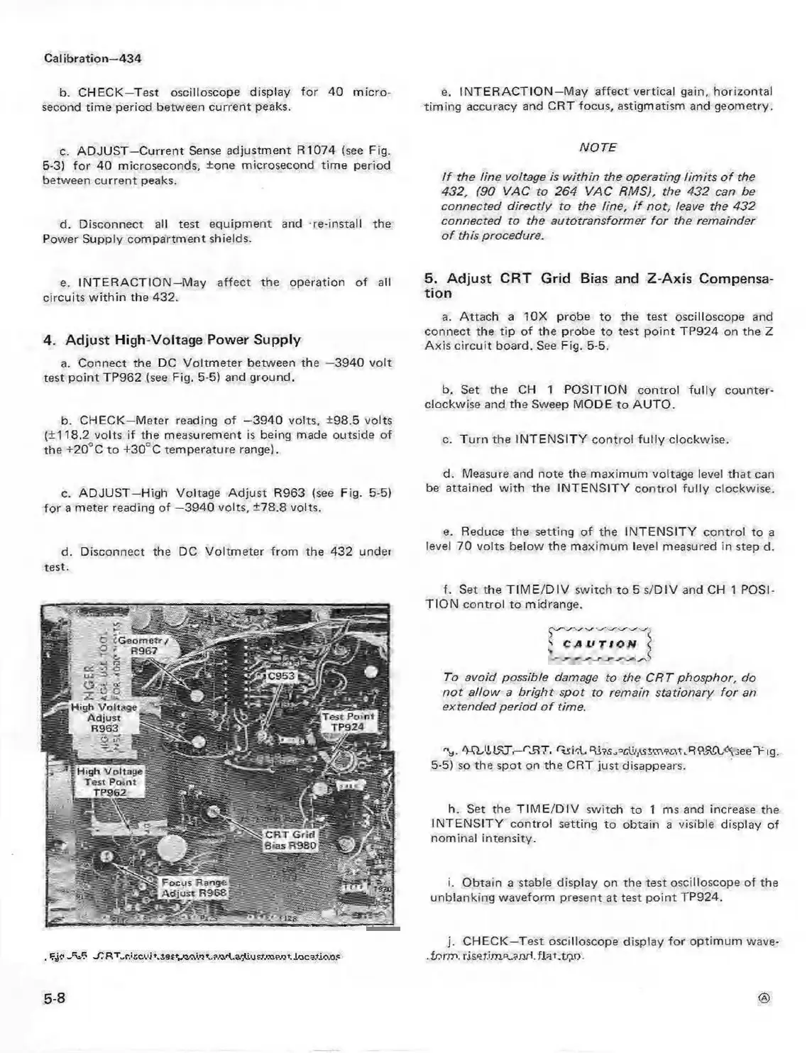
a. Connect the DC Voltmeter between the —3940 volt
test point TP962 (see Fig. 5-5) and ground.
b. CHECK—Meter reading of —3940 volts, ±98.5 volts
(±118.2 volts if the measurement is being made outside of
the +20°C to +30"C temperature range).
c. ADJUST—High Voltage Adjust R963 (see Fig. 5-5)
for a meter reading of —3940 volts, ±78.8 volts.
d. Disconnect the DC Voltmeter from the 432 under
test.
. irj? J U ? JC R T„ r , 's c v i\ l9 f V ^ '. '3 t~?.,i+.a'^usX TO p/?*. Io c ? tio .o 5
e. INTER AC TIO N —May affect vertical gain, horizontal
timing accuracy and CRT focus, astigmatism and geometry.
NOTE
I f the line voltage is w ithin the operating lim its o f the
432, (90 VAC to 264 VAC RMS), the 432 can be
connected directly to the line, i f not, leave the 432
connected to the autotransformer fo r the remainder
o f this procedure.
5. Adjust CRT Grid Bias and Z-Axis Compensa
tion
a. Attach a 10X probe to the test oscilloscope and
connect the tip of the probe to test point TP924 on the Z
Axis circuit board. See Fig. 5-5.
b. Set the CH 1 POSITION control fu lly counter
clockwise and the Sweep MODE to AUTO.
c. Turn the INTENSITY control fu lly clockwise.
d. Measure and note the maximum voltage level that can
be attained w ith the INTENSITY control fully clockwise.
e. Reduce the setting of the INTENSITY control to a
level 70 volts below the maximum level measured in step d.
f. Set the T IM E/D IV switch to 5 s/DIV and CH 1 POSI
TIO N control to midrange.
s c. a u Ttt!N <
To avoid possible damage to the CRT phosphor, do
no t allow a bright spot to remain stationary fo r an
extended period o f time.
*V AQJA 1STi—ORT. 'Trirl.R i^s^^ctvjrstm rat.RPfKL^jeeTig.
5-5) so the spot on the CRT just disappears.
h. Set the T IM E /D IV switch to 1 ms and increase the
INTEN SITY control setting to obtain a visible display of
nominal intensity.
i. Obtain a stable display on the test oscilloscope of the
unblanking waveform present at test point TP924.
j. CHECK—Test oscilloscope display fo r optimum wave-
.for.m. riset.ijne„and.fiat.tpo.
<8>
5-8