Maintenance—434
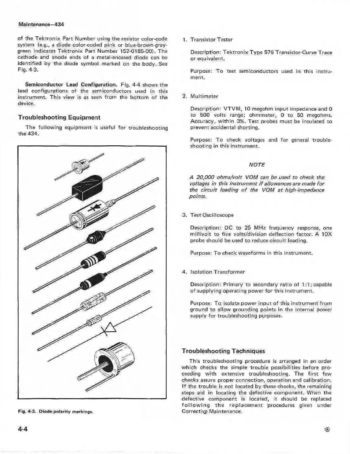
of the T ektronix Part Number using the resistor color-code
system (e.g., a diode color-coded pink or blue-brown-gray-
green indicates T ektronix Part Number 152-0185-00). The
cathode and anode ends of a metal-encased diode can be
identified by the diode symbol marked on the body. See
Fig. 4-3.
Semiconductor Lead Configuration. Fig, 4-4 shows the
lead configurations of the semiconductors used in this
instrument. This view is as seen from the bottom o f the
device.
Troubleshooting Equipment
The following equipment is useful for troubleshooting
the 434.
Fig. 4-3. Diode p o la rity m arkings.
1. Transistor Tester
Description: Tektronix Type 576 Transistor-Curve Trace
or equivalent.
Purpose: To test semiconductors used in this instru
ment.
2. M ultimeter
Description: VTVM , 10 megohm input impedance and 0
to 500 volts range; ohmmeter, 0 to 50 megohms.
Accuracy, w ith in 3%. Test probes must be insulated to
prevent accidental shorting.
Purpose: To check voltages and for general trouble
shooting in this instrument.
NOTE
A 20,000 ohm s/vott VOM can be used to check the
voltages in this instrum ent i f allowances are made fo r
the c ircuit loading o f the VOM at high-impedance
points.
3. Test Oscilloscope
Description: DC to 25 MHz frequency response, one
m illivo lt to five volts/division deflection factor. A 10X
probe should be used to reduce circuit loading.
Purpose: To check waveforms in this instrument.
4. Isolation Transformer
Description: Primary to secondary ratio of 1:1; capable
of supplying operating power for this instrument.
Purpose: To isolate power input of this instrument from
ground to allow grounding points in the internal power
supply for troubleshooting purposes.
Troubleshooting Techniques
This troubleshooting procedure is arranged in an order
which checks the simple trouble possibilities before pro
ceeding w ith extensive troubleshooting. The first few
checks assure proper connection, operation and calibration.
If the trouble is not located by these checks, the remaining
steps aid in locating the defective component. When the
defective component is located, it should be replaced
fo llo w in g the replacem ent procedures given under
Corrective Maintenance.
4-4