Calibration—434
TRIGGER CIRCUIT ADJUSTMENT
Equipment Required
1. Med i u m-F requ ency Constant-Amplitude Signal
4. BNC T Connector
Generator
5. 42-Inch 50 f t BNC Cable (two required)
2. Low-Frequency Signal Generator
6. 3-Inch Screwdriver
3. 50 f t BNC Term ination
Control Settings
Preset the instrument controls to the settings given
under Preliminary Control Settings except as follows:
Sweep MODE AUTO
TIME/D1V 50 ms
INTENSITY Visible Display
28. Adjust Trigger Level Centering
a. Connect the output of the Medium-Frequency
Constant-Amplitude Signal Generator to the CH 1 input
connector via a GR to BNC adapter, a 42-inch 50 ft BNC
cable, and a 50 f t BNC term ination.
b. Adjust the output of the signal generator fo r a 0.3-
division display of the 50 kilohertz reference frequency.
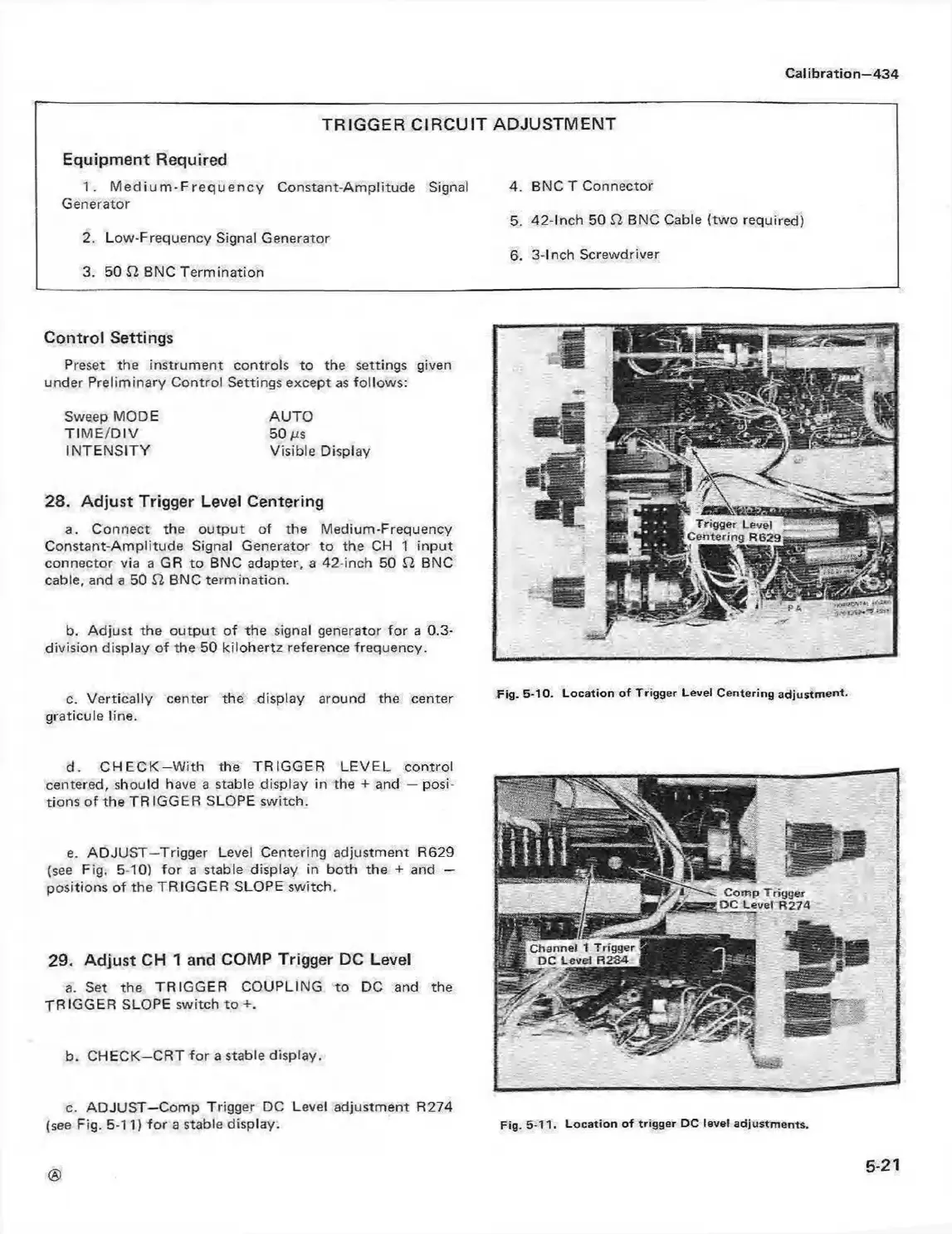
c. Vertically center the display around the center Fig. 5-10. Loca tion o f Trigger Level Centering adjustm ent,
graticule line.
d. C H E C K -W ith the TRIGGER LE VEL control
centered, should have a stable display in the + and — posi
tions o f the TR IGGER SLOPE switch.
e. ADJUST—Trigger Level Centering adjustment R629
(see Fig, 5-10) fo r a stable display in both the + and —
positions of the TRIGGER SLOPE switch.
29. Adjust CH 1 and COMP Trigger DC Level
a. Set the TRIGGER COUPLING to DC and the
TR IGGER SLOPE switch to +.
b. CHECK—CRT fo r a stable display.
c. ADJUST—Comp Trigger DC Level adjustment R274
(see Fig. 5-11) fo r a stable display.
5-21
Fig. 5-11. L ocation o f trigger DC level adjustm ents.