C ircuit Description—434
CALIB RA TO R
General
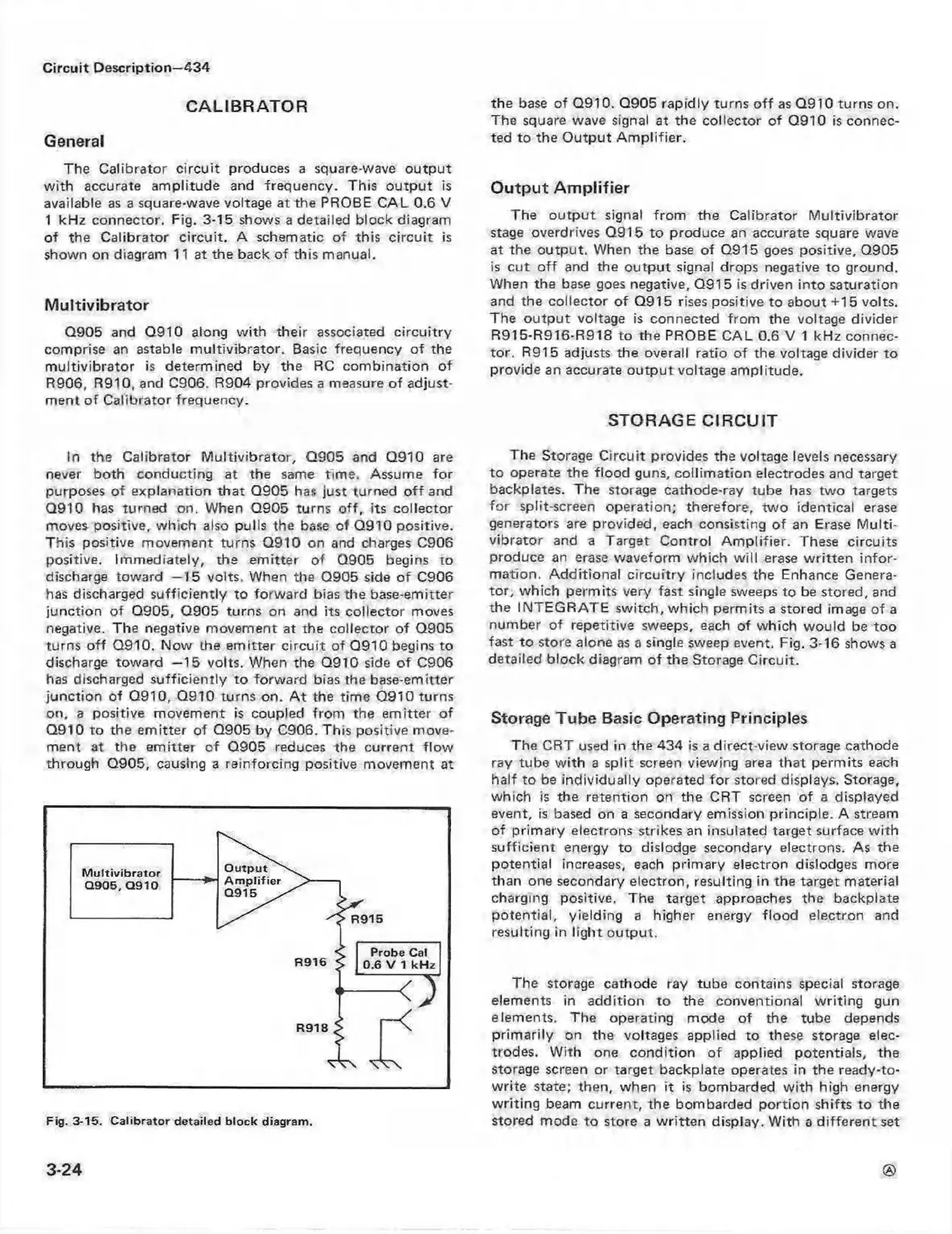
The Calibrator circu it produces a square-wave outpu t
w ith accurate am plitude and frequency. This o utpu t is
available as a square-wave voltage at the PROBE CA L 0.6 V
1 kHz connector. Fig. 3-15 shows a detailed block diagram
of the C alibrator circu it. A schematic of this circu it is
shown on diagram 11 at the back of this manual.
M ultivibrator
Q905 and Q910 along w ith their associated circuitry
comprise an astable m u ltivib rator. Basic frequency of the
m ultivibrato r is determined by the RC com bination of
R906, R910, and C906. R904 provides a measure o f adjust
ment o f C alibrator frequency.
In the C alibrator M ultivibrator, Q905 and Q910 are
never both conducting at the same tim e. Assume fo r
purposes o f explanation tha t Q905 has just turned o ff and
Q910 has turned on. When Q905 turns o ff, its collector
moves positive, which also pulls the base of Q910 positive.
This positive movement turns Q910 on and charges C906
positive. Im mediately, the em itter of Q905 begins to
discharge toward —15 volts. When the Q905 side of C906
has discharged sufficiently to forw ard bias the base-emitter
junction of Q905, Q905 turns on and its collector moves
negative. The negative movem ent at the collector of Q905
turns o ff Q910. Now the em itter circu it of Q910 begins to
discharge toward —15 volts. When the Q910 side of C906
has discharged sufficiently to forward bias the base-emitter
junction of Q910, Q910 turns on. A t the tim e Q910 turns
on, a positive movement is coupled from the em itter of
Q910 to the em itter of Q905 by C906. This positive move
ment at the em itter of Q905 reduces the current flo w
through Q905, causing a reinforcing positive movem ent at
Fig. 3-15. C a lib ra to r detailed bloc k diagram .
the base of Q910. Q905 rapidly turns o ff as Q910 turns on.
The square wave signal at the collector of Q910 is connec
ted to the O utput A m p lifier.
O utput A m plifie r
The o u tp u t signal from the C alibrator M ultivibrator
stage overdrives Q915 to produce an accurate square wave
at the output. When the base o f Q915 goes positive, Q905
is cu t o ff and the outpu t signal drops negative to ground.
When the base goes negative, Q915 is driven in to saturation
and the collector of Q915 rises positive to about +15 volts.
The o u tpu t voltage is connected from the voltage divider
R915-R916-R918 to the PROBE C AL 0.6 V 1 kH z connec
tor. R915 adjusts the overall ratio of the voltage divider to
provide an accurate o utpu t voltage amplitude.
STORAGE C IRCU IT
The Storage C ircuit provides the voltage levels necessary
to operate the flood guns, co llim a tion electrodes and target
backplates. The storage cathode-ray tube has tw o targets
fo r split-screen operation; therefore, tw o identical erase
generators are provided, each consisting of an Erase M u lti
vibrator and a Target Control A m plifier. These circuits
produce an erase waveform w hich w ill erase w ritte n in fo r
m ation. A dd itional circuitry includes the Enhance Genera
to r, w hich permits very fast single sweeps to be stored, and
the INTEG R ATE switch, which perm its a stored image of a
number of repetitive sweeps, each of which would be too
fast to store alone as a single sweep event. Fig. 3-16 shows a
detailed block diagram of the Storage C ircuit.
Storage Tube Basic Operating Principles
The CRT used in the 434 is a direct-view storage cathode
ray tube w ith a split screen viewing area that permits each
half to be individually operated fo r stored displays. Storage,
which is the retention on the CRT screen of a displayed
event, is based on a secondary emission principle. A stream
of prim ary electrons strikes an insulated target surface w ith
sufficient energy to dislodge secondary electrons. As the
potential increases, each primary electron dislodges more
than one secondary electron, resulting in the target material
charging positive. The target approaches the backpiate
potential, yielding a higher energy flo od electron and
resulting in ligh t outpu t.
The storage cathode ray tube contains special storage
elements in addition to the conventional w riting gun
elements. The operating mode of the tube depends
prim arily on the voltages applied to these storage elec
trodes. W ith one con dition o f applied potentials, the
storage screen or target backpiate operates in the ready-to-
w rite state; then, when it is bombarded w ith high energy
w riting beam current, the bombarded portion shifts to the
stored mode to store a w ritten display. W ith a diffe ren t set
3-24
 Loading...


