Calibration—434
VER TICAL SYSTEM ADJUSTMENT
Equipment Required
1. Standard A m plitude Calibrator
7. Adapter (GR874 and BNC female connectors)
2. Square-Wave Generator
8. 50 £2 BNC Term ination
3. M ed iu m -F re q u e n c y Constant-Amplitude Signal
9. BNC T Connector
Generator
10. 3-Inch Screwdriver
4. 24 pF Input Normalizer
11. Low-Capacitance Screwdriver
5. 42-Inch 50 £2 BNC Cable (2 required)
12. Tuning Tool
6. BNC 50 £2 10X Attenuator
Control Settings
Preset the instrum ent controls to the settings given
under Preliminary Control Settings except as follows:
Sweep MODE
INTENSITY
Input Coupling
TRIGGER LEVEL
AUTO
For visible display
GND
Fully clockwise
17. Adjust Channel 1 Balance
a. Change the CH 1 VO LTS/D IV switch from 10 mV to
1 mV.
b. CHECK—CRT display for not more than 0.1 division
of trace shift when switching from 10 mV to 1 mV.
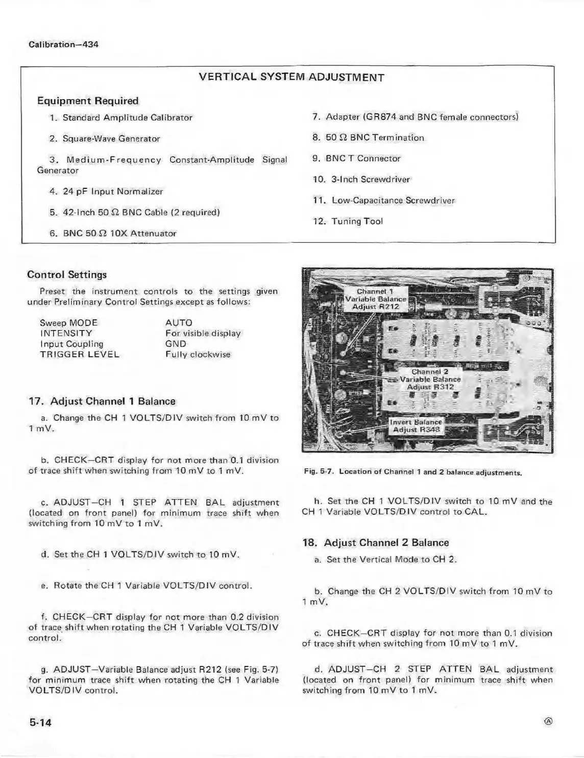
Channel 1
Variable Balance
Adjust R212
Channel 2
Variable Balance
Adjust R312
Invert Balance
A djust R348
ao«c
. - --
Fig. 5-7. Lo ca tion o f Channel 1 and 2 balance adjustm ents.
c. A D JU S T-C H 1 STEP ATTEN BAL adjustment
(located on front panel) for minimum trace shift when
switching from 10 mV to 1 mV.
d. Set the CH 1 VO LTS/D IV switch to 10 mV.
e. Rotate the CH 1 Variable V O LTS /D IV control.
f. CHECK—CRT display for not more than 0.2 division
of trace shift when rotating the CH 1 Variable V O LTS/D IV
control.
g. ADJUST—Variable Balance adjust R212 (see Fig. 5-7)
for minimum trace shift when rotating the CH 1 Variable
VO LTS/D IV control.
h. Set the CH 1 VO LTS/D IV switch to 10 mV and the
CH 1 Variable VO LTS/D IV control to CAL.
18. Adjust Channel 2 Balance
a. Set the Vertical Mode to CH 2.
b. Change the CH 2 V O LTS/DIV switch from 10 mV to
1 mV.
c. CHECK—CRT display for not more than 0.1 division
of trace shift when switching from 10 mV to 1 mV.
d. A DJUST-C H 2 STEP ATTEN BAL adjustment
(located on fro n t panel) for minimum trace shift when
switching from 10 mV to 1 mV.
<§>
5-14