Operating Instructions—434
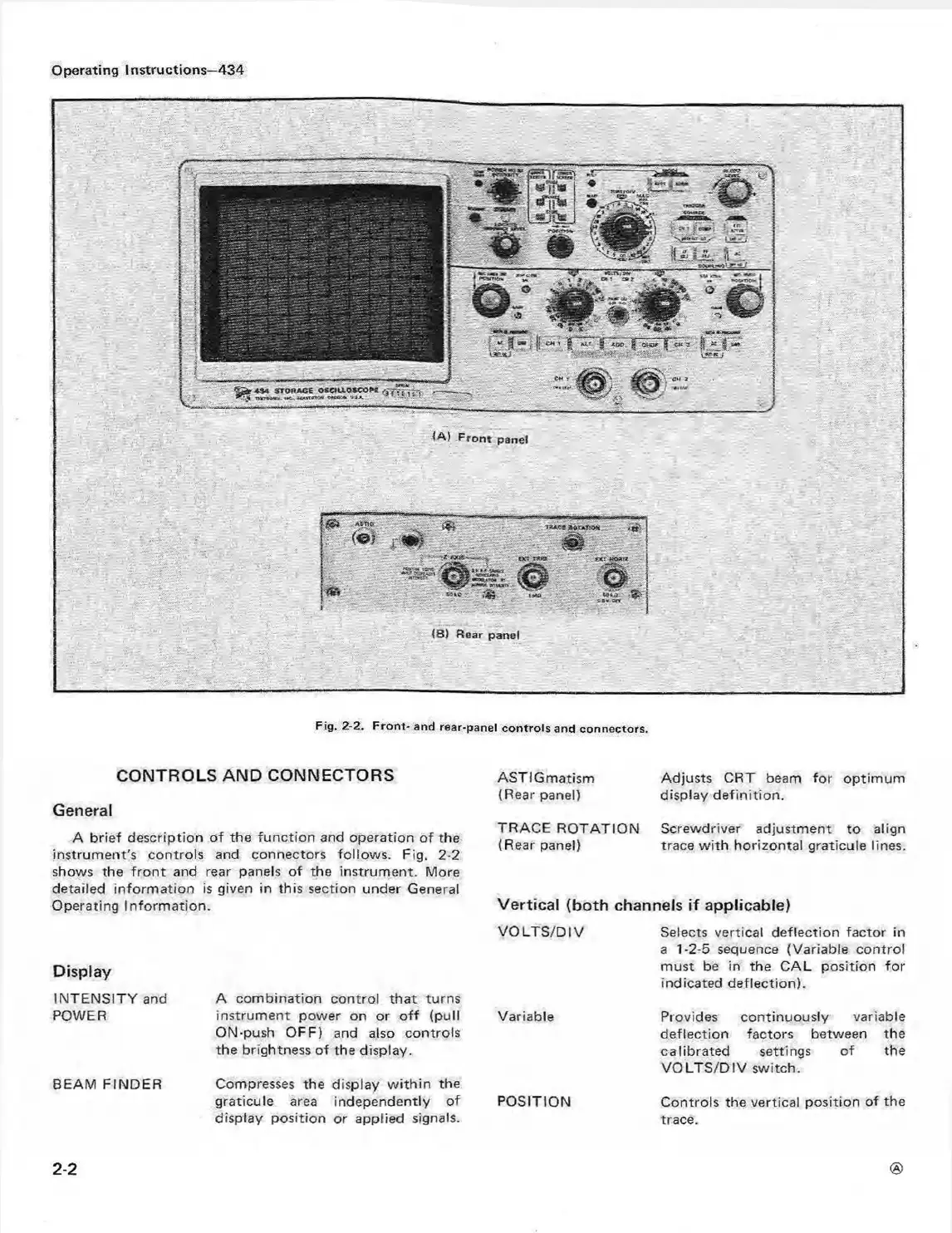
Fig. 2-2. F ront- and rear-pane! controls and connectors.
CONTROLS AND CONNECTORS
General
A brief description of the function and operation of the
instrument's controls and connectors follows. Fig. 2-2
shows the fro nt and rear panels of the instrument. More
detailed inform ation is given in this section under General
Operating Inform ation.
Display
INTENSITY and
POWER
BEAM FINDER
A combination control that turns
instrument power on or o ff (pull
ON-push OFF) and also controls
the brightness of the display.
Compresses the display w ithin the
graticule area independently of
display position or applied signals.
ASTIGmatism Adjusts CRT beam for optim um
(Rear panel) display definition.
TRACE ROTATION Screwdriver adjustment to align
(Rear panel) trace w ith horizontal graticule lines.
Vertical (both channels if applicable)
VO LTS/D IV Selects vertical deflection factor in
a 1-2-5 sequence (Variable control
must be in the CAL position for
indicated deflection).
Variable Provides continuously variable
deflection factors between the
calibrated settings of the
VO LTS/D IV switch.
POSITION
Controls the vertical position of the
trace.
2-2