Calibration—434
CALIBRATOR CIRCUIT ADJUSTMENT
Equipment Required
1. Precision DC Voltm eter
3. 42-Inch 50 Q. BNC Cable
2. Time-Mark Generator
4. 3-1 nch Screwdriver
Control Settings
Preset the Instrument controls to the settings given
under Preliminary Control Settings except as follows:
Sweep MODE ' AUTO
INTENSITY Visible Display
Vertical Mode A LT
44. Adjust Calibrator Output Voltage Am plitude
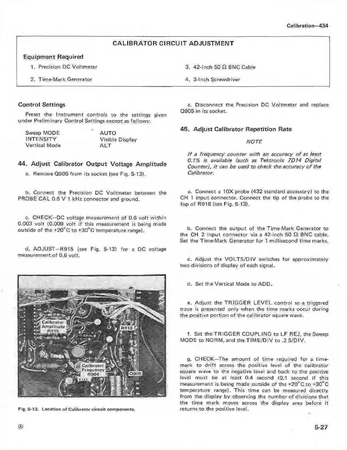
a. Remove Q905 from its socket (see Fig. 5-13).
e. Disconnect the Precision DC Voltmeter and replace
Q905 in its socket.
45. Adjust Calibrator Repetition Rate
NOTE
I f a frequency counter with an accuracy o f at least
0.1% is available (such as Tektronix 7D14 Digital
Counter), it can be used to check the accuracy o f the
Calibrator.
b. Connect the Precision DC Voltm eter between the
PROBE CAL 0.6 V 1 kHz connector and ground.
a. Connect a 10X probe (432 standard accessory) to the
CH 1 input connector. Connect the tip of the probe to the
top of R918 (see Fig. 5-13).
c. CHECK—DC voltage measurement of 0.6 volt w ithin
0.003 volt (0.009 volt if this measurement is being made
outside o f the +20° C to +30"'C temperature range).
d. ADJUST—R915 (see Fig. 5-13) for a DC voltage
measurement of 0.6 volt.
b. Connect the output of the Time-Mark Generator to
the CH 2 input connector via a 42-inch 50 Cl BNC cable.
Set the Time-Mark Generator fo r 1 millisecond time marks.
c. Adjust the VO LTS/D IV switches for approximately
two divisions of display of each signal.
Fig. 5-13. L ocation o f C a libra tor c irc u it com ponents.
d. Set the Vertical Mode to ADD.
e. Adjust the TRIGGER LEVEL control so a triggered
trace is presented only when the time marks occur during
the positive portion o f the calibrator square wave.
f. Set the TRIGGER COUPLING to LF REJ, the Sweep
MODE to NORM, and the TIM E /D IV to .2 S/DIV.
g. CHECK—The amount of time required for a time-
mark to d rift across the positive level of the calibrator
square wave to the negative level and back to the positive
level must be at least 0.4 second (0.1 second if this
measurement is being made outside of the +20°C to + 3 0 ^
temperature range). This time can be measured directly
from the display by observing the number of divisions that
the time mark moves across the display area before it
returns to the positive level.
5-27