d. Set the TRIGGER SOURCE to CH 1.
Calibration—434
e. CHECK—CRT for a stable display.
f. ADJUST—CH 1 Trigger DC Level adjustment R284
(see Fig. 5-11) for a stable display.
30. Check Trigger Circuit Operation
a. Connect the signal from the signal generator to the
CH 1 input connector via a GR to BNC adapter, a 42-inch
50 12 BIMC cable, and a BNC T connector. Connect the
unused ou tput of the BNC T connector to the EXT TRIG
input connector via a 42-inch 50 12 BNC cable and a 50 12
BNC term ination.
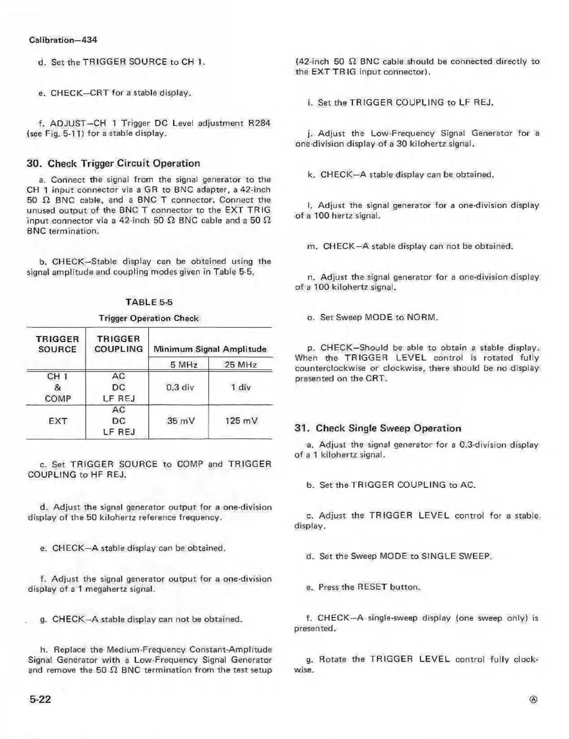
b. CHECK—Stable display can be obtained using the
signal amplitude and coupling modes given in Table 5-5.
TABLE 5-5
Trigger Operation Check
TRIGGER
SOURCE
TRIGGER
COUPLING Minimum Signal A m plitude
5 MHz
25 MHz
CH 1
&
COMP
AC
DC
LF REJ
0.3 div
1 div
EXT
AC
DC
LF REJ
35 mV
125 mV
c. Set TRIGG ER SOURCE to COMP and TRIGGER
COUPLING to HF REJ.
d. Adjust the signal generator output for a one-division
display of the 50 kilohertz reference frequency.
e. CHECK—A stable display can be obtained.
f. Adjust the signal generator output for a one-division
display of a 1 megahertz signal.
g. CHECK—A stable display can not be obtained.
h. Replace the Medium-Frequency Constant-Amplitude
Signal Generator w ith a Low-Frequency Signal Generator
and remove the 50 12 BNC term ination from the test setup
(42-inch 50 12 BNC cable should be connected directly to
the EXT TR IG input connector).
i. Set the TRIGGER COUPLING to LF REJ.
j. Adjust the Low-Frequency Signal Generator for a
one-division display of a 30 kilohertz signal.
k. CHECK—A stable display can be obtained.
I. Adjust the signal generator for a one-division display
of a 100 hertz signal.
m. CHECK—A stable display can not be obtained.
n. A djust the signal generator for a one-division display
of a 100 kilohertz signal.
o. Set Sweep MODE to NORM.
p. CHECK—Should be able to obtain a stable display.
When the TRIGGER LEVEL control is rotated fully
counterclockwise or clockwise, there should be no display
presented on the CRT.
31. Check Single Sweep Operation
a. Adjust the signal generator for a 0.3-division display
of a 1 kilohertz signal.
b. Set the TRIGGER COUPLING to AC.
c. Adjust the TRIGGER LEVEL control fo r a stable
display.
d. Set the Sweep MODE to SINGLE SWEEP.
e. Press the RESET button.
f. CHECK—A single-sweep display (one sweep only) is
presented.
g. Rotate the TRIGGER LEVEL control fu lly clock
wise.
5-22