C alibration—434
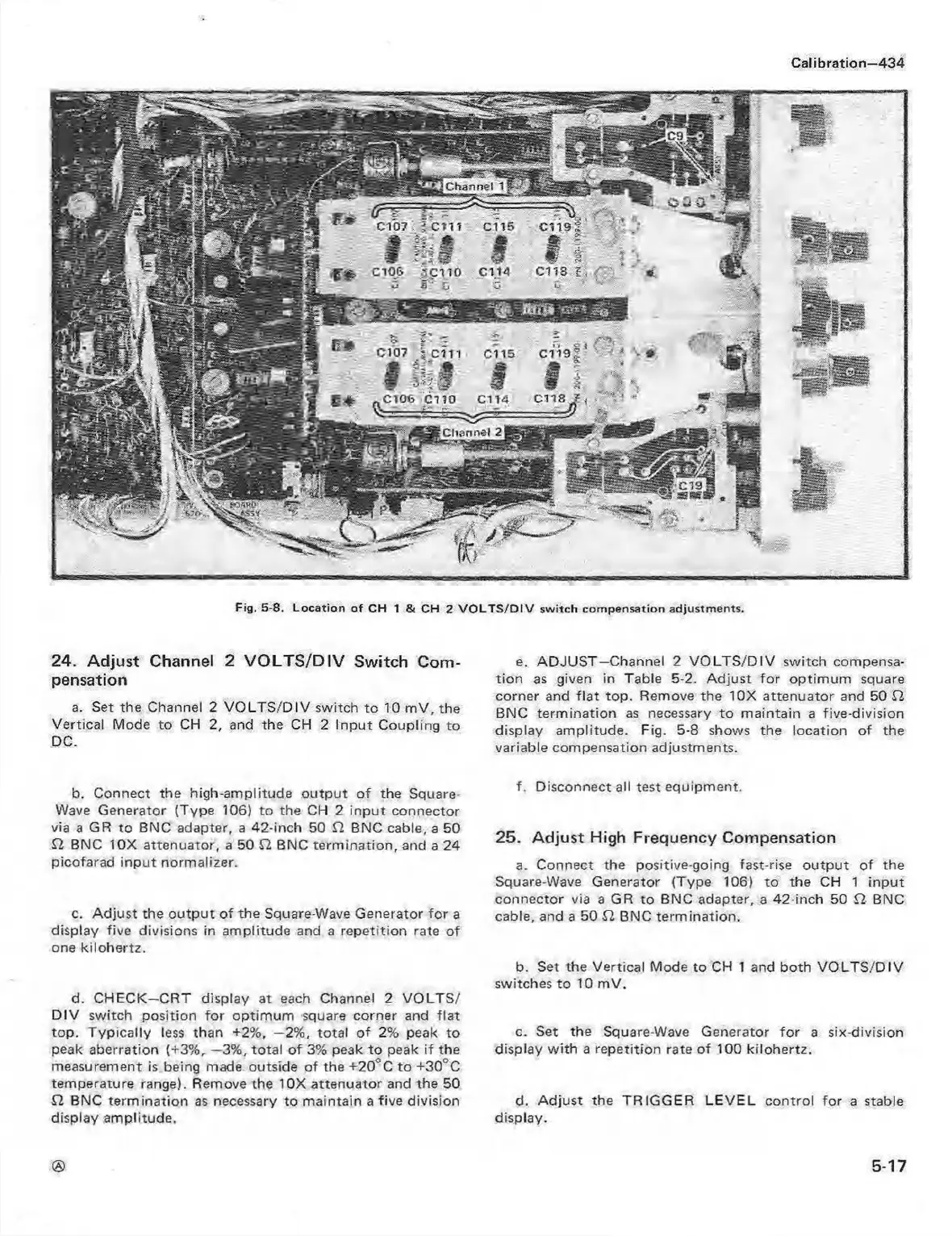
Fig. 5-8. L o cation o f CH 1 & CH 2 V O L T S /D IV s w itch com p en sation adjustm ents.
24. Adjust Channel 2 V O LT S/D IV Switch Com
pensation
a. Set the Channel 2 V O LT S /D IV switch to 10 m V, the
Vertical Mode to CH 2, and the CH 2 In put Coupling to
DC.
b. Connect the high-amplitude o utpu t o f the Square-
Wave Generator (Type 106) to the CH 2 inp ut connector
via a GR to BNC adapter, a 42-inch 50 £2 BNC cable, a 50
£2 BNC 10X attenuator, a 50 £2 BNC term ination, and a 24
picofarad inpu t normalizer.
c. A djust the o utpu t of the Square-Wave Generator fo r a
display five divisions in am plitude and a repetition rate of
one kilohertz.
d. CHECK—CRT display at each Channel 2 VO LTS /
D IV switch position for optim um square corner and fla t
top. Typically less than +2%, —2%, total of 2% peak to
peak aberration (+3%, —3%, total o f 3% peak to peak if the
measurement is being made outside of the +20° C to +30°C
temperature range). Remove the 10X attenuator and the 50
£2 BNC term ination as necessary to maintain a five division
display am plitude.
e. A D JUST—Channel 2 V O LT S /D IV switch compensa
tion as given in Table 5-2. A djust fo r optim um square
corner and fla t top. Remove the 10X attenuator and 50 £2
BNC term ination as necessary to m aintain a five-division
display amplitude. Fig. 5-8 shows the location of the
variable compensation adjustments.
f. Disconnect all test equipment.
25. Adjust High Frequency Compensation
a. Connect the positive-going fast-rise o utput of the
Square-Wave Generator (Type 106) to the CH 1 input
connector via a GR to BNC adapter, a 42-inch 50 £2 BNC
cable, and a 50 £2 BNC term ination.
b. Set the Vertical Mode to CH 1 and both VO LT S /D IV
switches to 10 mV.
c. Set the Square-Wave Generator fo r a six-division
display w ith a repetition rate of 100 kilohertz.
d. Adjust the TRIG G ER LE VE L control for a stable
display.
5-17