Operating Instructions—434
NO TE
For low-frequency signals below about 100 hertz, use
the DC po sition to prevent attenuation.
5. Set the TR IG G ERING controls to obtain a stable
display. Set the T IM E /D IV switch to a position that dis
plays several cycles of the waveform .
EXA M PLE . Assume that the peak-to-peak vertical
deflection is 4.6 divisions (see Fig. 2-7) w ith a VO LT S /D IV
switch setting of .5 V.
Volts
Peak to Peak
vertical
= deflection
(divisions)
V O L TS /D IV
setting
Substituting the given values:
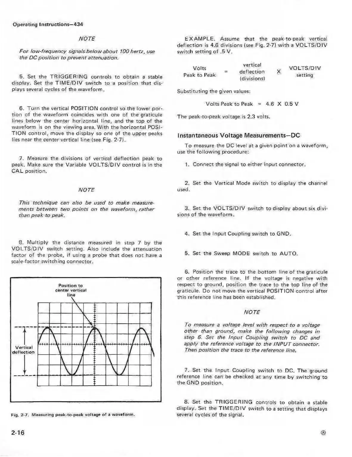
6. Turn the vertical POSITION control so the lower p or
tion of the waveform coincides w ith one of the graticule
lines below the center horizontal line, and the top of the
waveform is on the viewing area. W ith the horizontal POSI
TIO N control, move the display so one of the upper peaks
lies near the center vertical line (see Fig. 2-7).
7. Measure the divisions of vertical deflection peak to
peak. Make sure the Variable V O L TS /D IV control is in the
CAL position.
Volts Peak to Peak = 4.6 X 0.5 V
The peak-to-peak voltage is 2.3 volts.
Instantaneous Voltage Measurements—DC
To measure the DC level at a given po int on a waveform ,
use the follow ing procedure:
1. Connect the signal to either input connector.
2. Set the Vertical Mode switch to display the channel
NO TE used.
This technique can also be used to make measure
ments between tw o points on the waveform, rather 3. Set the V O LTS /D IV switch to display about six divi-
than peak to peak. sions of the waveform .
8. M ultiply the distance measured in step 7 by the
V O L TS /D IV switch setting. Also include the attenuation
factor of the probe, if using a probe that does not have a
scale-factor switching connector.
Fig. 2-7. M easuring peak-to-peak voltage o f a w avefo rm .
4. Set the Input Coupling switch to GND.
5. Set the Sweep MODE switch to AUTO.
6. Position the trace to the bottom line of the graticule
or other reference line. If the voltage is negative w ith
respect to ground, position the trace to the top line of the
graticule. Do not move the vertical POSITION control after
this reference line has been established.
NOTE
To measure a voltage level w ith respect to a voltage
other than ground, make the fo llow ing changes in
step 6. Set the In p u t Coupling switch to DC and
apply the reference voltage to the IN P U T connector.
Then position the trace to the reference line.
7. Set the Input Coupling switch to DC. The ground
reference line can be checked at any tim e by switching to
the GND position.
8. Set the TR IG G ER IN G controls to obtain a stable
display. Set the T IM E /D IV switch to a setting that displays
several cycles of the signal.
2-16 ®