Maintenance—434
1. Check Control Settings. Incorrect control settings
can indicate a trouble that does not exist. If there is any
question about the correct fun ction or operation of any
control, see the Operating Instructions section.
2. Check Associated Equipment. Before proceeding
w ith troubleshooting of the 434, check tha t the equipm ent
used w ith this instrum ent is operating correctly. Check that
the signal is properly connected and tha t the inter
connecting cables are not defective. Also, check the power
source.
3. Visual Check. Visually check the po rtion of the
instrum ent in which the trouble is located. Many troubles
can be located by visual indications such as unsoldered
c o n n e c tio n s , broken wires, damaged circu it boards,
damaged components, etc.
4. Check Instrument Calibration. Check the calibration
of this instrum ent, or the affected circuit if the trouble
appears in one circuit. The apparent trouble may only be a
result of misadjustment or may be corrected by calibration.
Complete calibration instructions are given in the Calibra
tion section.
5. Isolate Trouble to a Circuit. To isolate trouble to a
circuit, note the trouble sym ptom . The sym ptom often
identifies the circu it in which the trouble is located. For
exam ple, poor focus indicates that the CRT c ircu it
(includes high voltage) is probably at fault. When trouble
symptoms appear in more than one circuit, check affected
circuits by taking voltage and waveform readings.
Incorrect operation o f all circuits often indicates trouble
in the power supply. Check firs t fo r correct voltage o f the
individual supplies. However, a defective component else
where in the instrum ent can appear as a power-supply
trouble and may also affect the operation of other circuits.
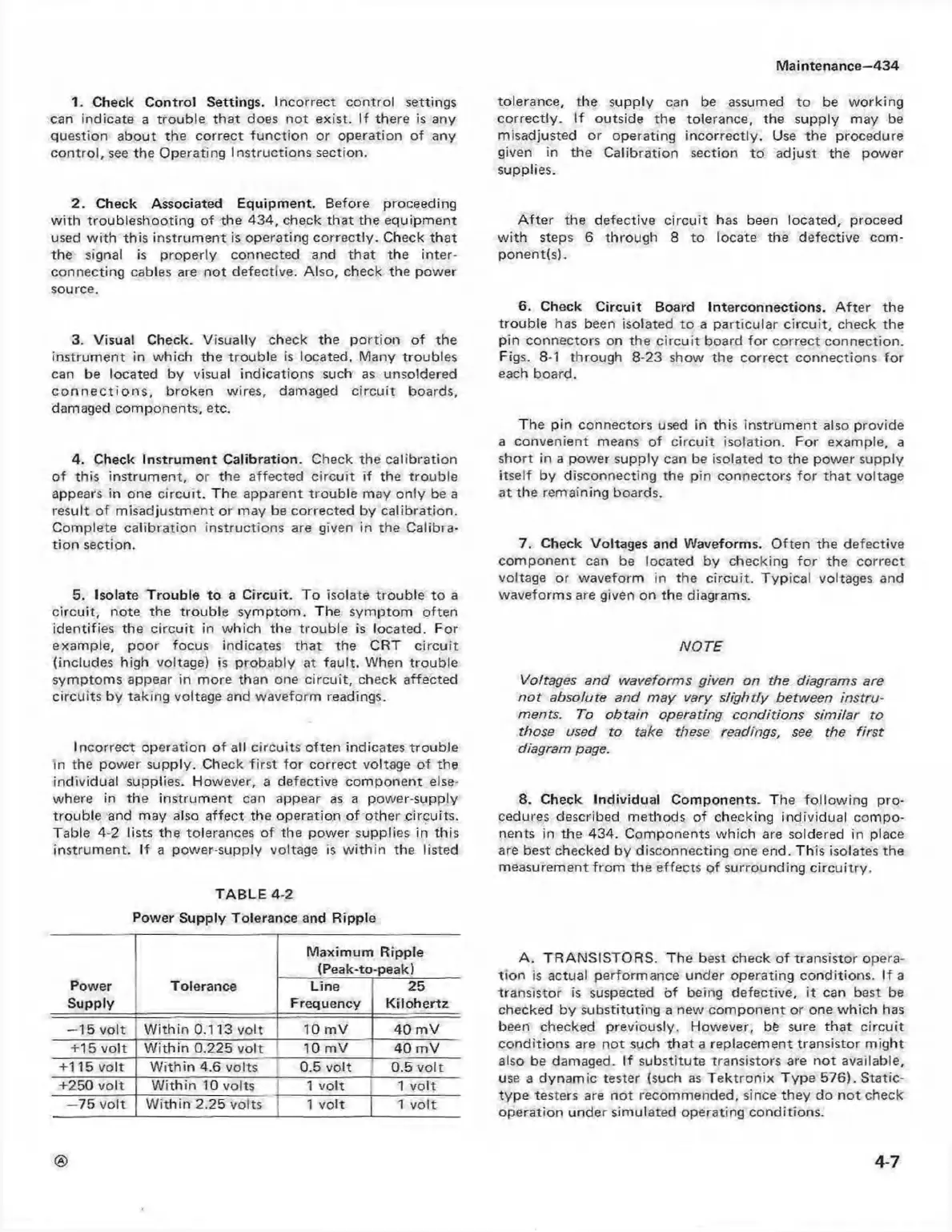
Table 4-2 lists the tolerances of the power supplies in this
instrum ent. If a power-supply voltage is w ith in the listed
TABLE 4-2
Power Supply Tolerance and Ripple
Power
Supply
Tolerance
Maximum Ripple
(Peak-to-peak)
Line
Frequency
25
Kilohertz
—15 volt
W ithin 0.113 volt 10 mV
40 m V
+15 vo lt W ithin 0.225 volt 10 mV 40 m V
+115 volt W ithin 4.6 volts
0.5 volt 0.5 vo lt
+250 volt W ithin 10 volts
1 volt 1 volt
—75 volt W ithin 2.25 volts 1 volt
1 vo lt
tolerance, the supply can be assumed to be w orking
correctly. If outside the tolerance, the supply may be
misadjusted or operating incorrectly. Use the procedure
given in the Calibration section to adjust the power
supplies.
A fte r the defective circuit has been located, proceed
w ith steps 6 through 8 to locate the defective com
ponents).
6. Check Circuit Board Interconnections. A fter the
trouble has been isolated to a particular circ uit, check the
pin connectors on the circu it board for correct connection.
Figs. 8-1 through 8-23 show the correct connections for
each board.
The pin connectors used in this instrum ent also provide
a convenient means of circu it isolation. For example, a
short in a power supply can be isolated to the power supply
itself by disconnecting the pin connectors for tha t voltage
at the remaining boards.
7. Check Voltages and Waveforms. O ften the defective
com ponent can be located by checking fo r the correct
voltage or waveform in the circuit. Typical voltages and
waveforms are given on the diagrams.
NO TE
Voltages and waveforms given on the diagrams are
n o t absolute and may vary slightly between instru
ments. To obtain operating conditions sim ilar to
those used to take these readings, see the firs t
diagram page.
8. Check Individual Components. The follow ing pro
cedures described methods of checking individual com po
nents in the 434. Components w hich are soldered in place
are best checked by disconnecting one end. This isolates the
measurement from the effects of surrounding circuitry.
A . TRANSISTORS. The best check o f transistor opera
tion is actual performance under operating conditions. If a
transistor is suspected of being defective, it can best be
checked by substituting a new component or one w hich has
been checked previously. However, be sure th at circu it
conditions are not such that a replacement transistor m ight
also be damaged. If substitute transistors are not available,
use a dynam ic tester (such as T ektron ix Type 576). Static-
type testers are not recommended, since they do n o t check
operation under simulated operating conditions.
©
4-7