Brief Procedures (MSO70000/C Series, DSA/DPO70000B/C Series, and DPO7000 Series)
VerifytheA(M
ain) and B
(Delayed) Trigger Systems
Equipment required Prerequisites
< 4 GHz models: One precision 50 Ω coaxial
cable (Item 4)
< 4 GHz models:
One BNC to Minigrabber
adapter (item 18)
≥ 4 GHz models: One SMA cable (item 21)
≥ 4 GHz models
: One adapter (item 19)
None
1. Initialize t he instrument: Push the front-panel Default Setup button.
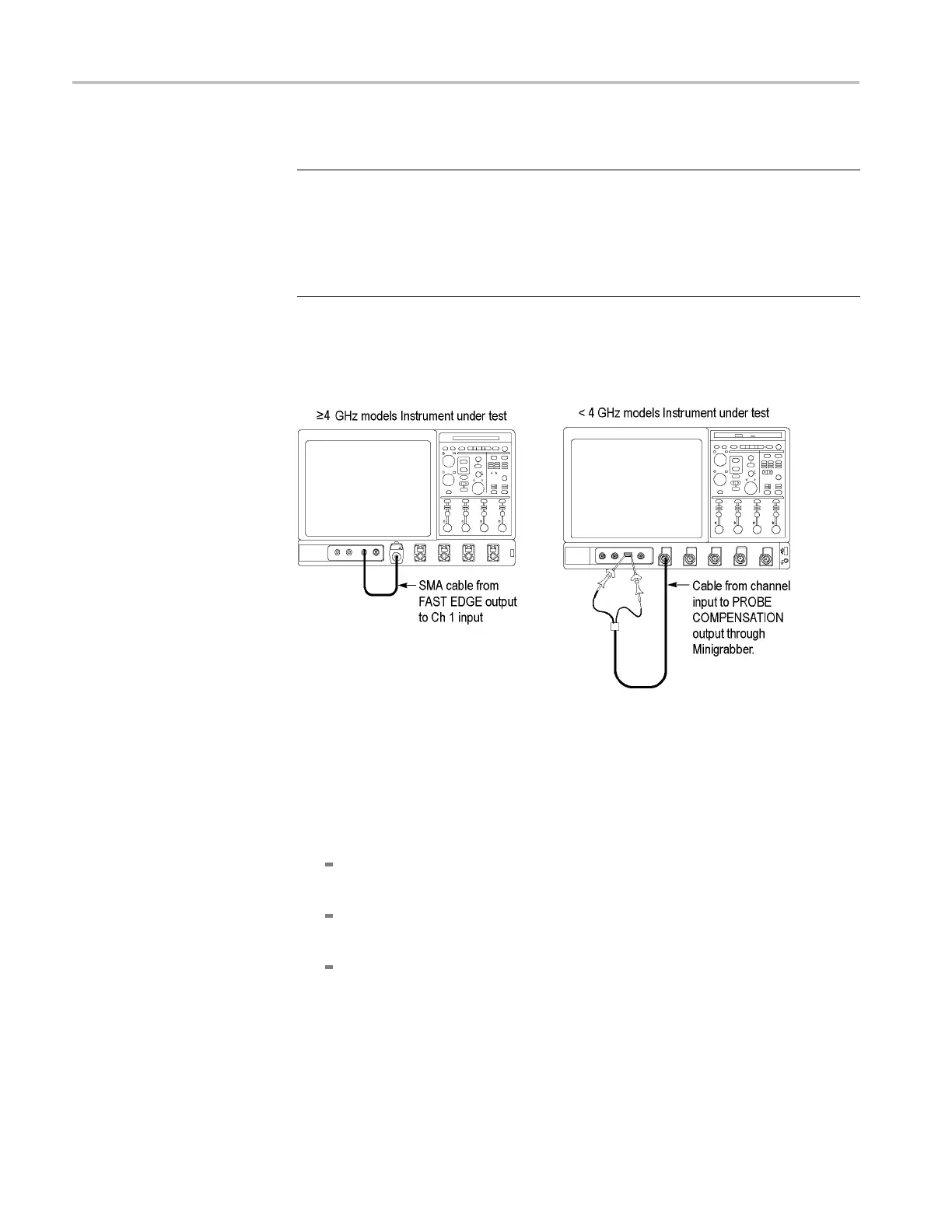
2. Hook up the signal source: Connect the probe compensation or fast edge
output to the Ch 1 input as shown in the following figure.
Figure 3-5: Setup for trigger test
3. Set u p the instrument: Push the front-panel Autoset button.
4. Set the Vertic al Sca le to 200 mV per division.
5. Verify that the main trigger system operates: Confirm that the following
statements are true.
The trigger level readout for the A (main) trigger system changes with the
trigger-Level knob.
The trigger-Level knob can trigger and untrigger the square-wave signal
as you rotate the knob. (Leave the signal untriggered).
Pushing the front-panel trigger Level knob sets the trigger level to the
50% amplitude point of the signal and triggers the signal that you just left
untriggered. (Leave the signal triggered.)
3–12 MSO70000/C, DSA70000B/C, DPO7000B/C, DPO7000, MSO5000, DPO5000 Series

 Loading...


