Performance Tests (MSO/DPO5000 Series)
16. Repeat the proc
edure for all remaining channels as follows:
a. Push the front-panel button to deselect the channel that you have already
tested.
b. Push the front-panel button to select the next channel to be tested.
c. Move the DC voltage source connection to the channel input to be tested.
d. Starting from step 3, repeat the procedure until all channels have been
tested.
17. Press the Menu Off button.
Check Analog Bandwidth
This test checks the bandwidth at 50 Ω and 1 M Ω for each channel.
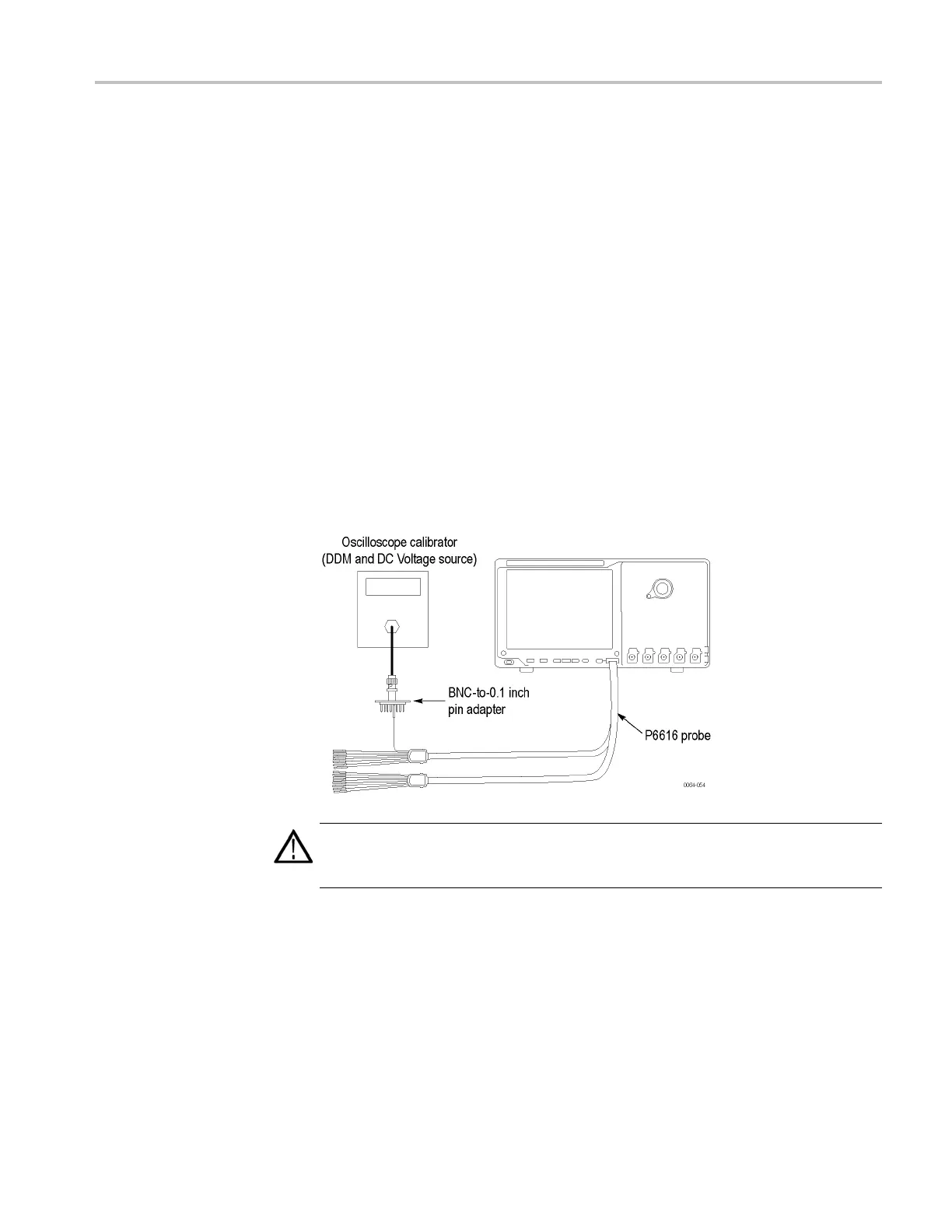
1. Connect the output of the leveled sine wave generator (for example, Fluke
9500) to the oscilloscope channel 1 input as shown in the following
illustration.
WARNING. The generator is capable of providing dangerous voltages. Be sure to
set the generator to off or 0 volts before connecting, disconnecting, and/or moving
the test hookup during the performance of this procedure.
3. Push the front-panel Default Setup button.
4. Set the impedance to 50 Ω as follows:
a. Set the calibrator to 50 Ω output impedance, and to generate a sine wave.
b. Push the front-panel oscilloscope Vertical Menu button.
c. Under Termination, click 50 Ω.
MSO70000/C, DSA70000B/C, DPO7000B/C, DPO7000, MSO5000, DPO5000 Series 4–35

 Loading...


