Performance Tests (MSO70000/C Series, DSA/DPO70000B/C Series, and DPO7000 Series)
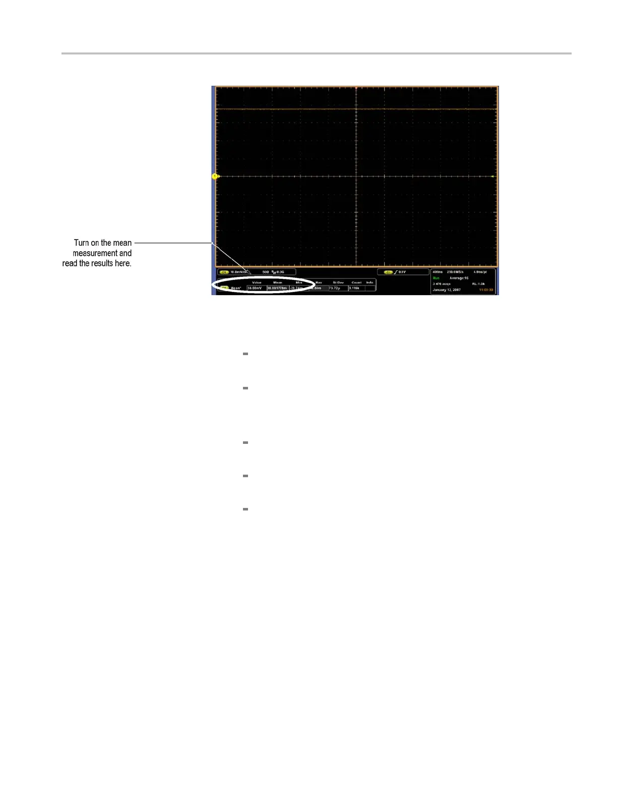
Figure 3-10: Measurement of DC gain accuracy
f. Measure second mean:
Set the generator to the second level and polarity indicated in the table
for the vertical scale, position, and o ffset settings you have made.
Repeat substep e using the current vertical scale, position, offset, and
new generator setting for the second mean.
g. Check against limits:
Subtract the second measurement mean from the first measurement
mean for the current vertical scale, position, and o ffset.
Record the difference of the two mean measurements i n the Difference
of Measurement Means column of the table. (See Table 3-5.)
CHECK that the Difference of Measurement Mean is within the limits
listed for the current vertical scale/position/offset/generator settings.
Enter measurement mean difference value on tes t record.
h. Repeat substeps d through g, using the next position, offset and generator
settings listed in the table for the current vertical scale.
i. Repeat substeps c through h until all vertical scale settings, listed in the
table, are checked for the channel under test. (See Table 3-5.)
j. Test all channels: Repeat substeps a through i for all four channels.
3. Disconnect the hookup:
a. Set the generator output to 0 V.
b. Disconnect the generator output from the channel l ast tested.
MSO70000/C, DSA70000B/C, DPO7000B/C, DPO7000, MSO5000, DPO5000 Series 3–55

 Loading...


