Performance Tests (MSO/DPO5000 Series)
Check Input Im
pedance (Resistance)
This test checks the Input Impedance.
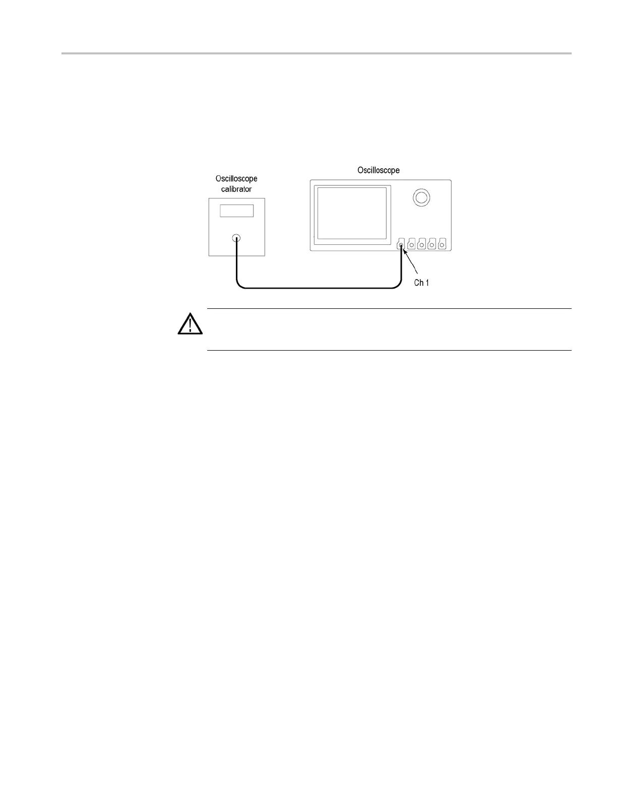
1. Connect the output of the oscilloscope calibrator (for example, Fluke 9500) to
the oscilloscope channel 1 input, as shown in the following illustration.
WARNING. The generator is capable of providing dangerous voltages. Be sure to
set the generator to off or 0 volts before connecting, disconnecting, and/or moving
the test hookup during the performance of this procedure.
2. Push the front-panel Default Setup button.
3. Set the impedance to 1 MΩ as follows:
a. Set the calibrator impedance to 1 MΩ.
b. Push the front-panel Vertical Menu button.
c. Set the Termination to 1MΩ.
4. Set the Ve rtical Scale to 10 mV/div.
5. Use the calibrator to measure the input impedance of the oscilloscope and
enter the value in the test record.
6. Repeat steps 4 and 5 for all vertical scale settings in the test record.
7. Repeat the tests at 250 kΩ as follows:
a. Set the calibrator impedance to 1 MΩ.
b. In the toolbar, click the Utilities menu and select Instrument Diagnostics.
c. Click the on-screeen Manual Product Verification button.
d. Click the on-screen box to Verify the p robe host terminations.
e. Set the Vertical Scale to 100 mV/division.
f. Use the calibrator to measure the input impedance of the oscilloscope and
enter the value in the test record.
MSO70000/C, DSA70000B/C, DPO7000B/C, DPO7000, MSO5000, DPO5000 Series 4–27

 Loading...


