Probe operating information
This section of the manual describes how to make connections to the instrument and to your circuit, followed by descriptions of the probe
controls and indicators.
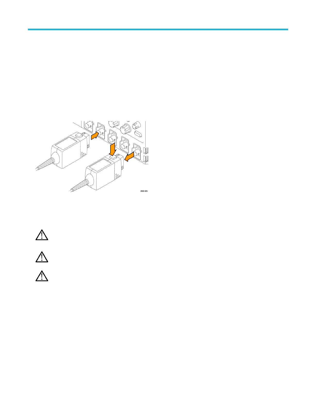
Connecting to the instrument
1. Connect the probe to the input of the oscilloscope.
• All of the LEDs on the probe body briefly light, and then indicate the settings from the previous session.
• The Status LED on the probe control box lights amber as the probe completes a self-test.
• The Status LED goes off briefly and then lights green to indicate the probe is ready to use.
2. Adjust the vertical of
fset (or position) of the oscilloscope input.
3. Select the proper range setting. For example, when using the THDP0200 probe, to achieve higher resolution and less noise when
measuring signals below 150 V
pk
, switch the RANGE to 150 V. If the OVERRANGE indicator lights or flashes, the output signal may
not be accurate. Use the 1500 V range setting instead.
WARNING: T
o avoid electrical shock, observe proper safety precautions when working with voltages above 60 VDC or
30 VAC
RMS
. These voltage levels pose a shock hazard. Use only the accessories specified with the probe that you are using.
Make sure that the accessories are fully mated before connecting or disconnecting.
WARNING: T
o avoid electrical shock or fire, make sure the test leads are in good condition. The input leads and extender
leads have a jacket wear indicator which becomes visible if the wire jacket becomes excessively worn. If the wear indicator is
visible, do not use the probe. Contact Tektronix Service for repair or replacement.
WARNING: T
o avoid electrical shock or fire, keep the probe body and output cable of the probe away from the circuits being
measured. The probe body and output cable are not intended to be in contact with the circuits being measured.
4. Use the probe accessories to connect the probe inputs to the circuit points to be measured.
Probe operating information
14

 Loading...


