DC gain Accuracy
WARNING: Dangerous voltages will be present on the calibration generator output terminals and connection cables. Always verify
that the generator is in the standby mode before you make any connections to the generator
.
1. V
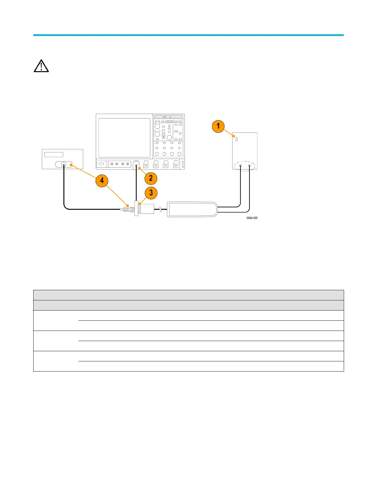
erify that the generator output is off.
2. Connect the probe calibration fixture to any channel (1–4) on the oscilloscope.
3. Connect the probe output to the probe calibration fixture and the probe inputs to the generator.
4. Connect the output of the probe calibration fixture to the inputs of the DMM, using coax cables and adapters. Set the DMM to AC volts.
5. Set the probe attenuation to the lower range for the probe that you are testing. See T
able 10 on page 48.
6. Set the generator square wave output frequency and RMS voltage (main display) to the values shown in the table for the probe that
you are testing.
7. Enable the generator output and record the probe output (as displayed on the DMM) in the test record.
8. Disable the generator output.
9. Set the probe attenuation to the next range and then repeat steps 6 on page 48 through 8 on page 48.
Table 10: DC gain accuracy equipment settings
Probe Generator output Probe output voltage
Model Range Voltage (rms) Frequency Expected (rms) Measured (rms)
THDP0100 600 V 75 V 100 Hz 750 mV ±15 mV
6000 V 75 V 100 Hz 75 mV ±15 mV
THDP0200 150 V 25 V 100 Hz 500 mV ±10 mV
1500 V 75 V 100 Hz 150 mV ±3 mV
TMDP0200 75 V 20 V 100 Hz 800 mV ±16 mV
750 V 60 V 100 Hz 240 mV ±4.8 mV
Performance verification
48

 Loading...


