Offset zero
This is the only procedure that applies to all of the probes and all serial numbers.
Adjustment notes
•
For probes with serial numbers C199999 and below, Offset Zero is the only adjustment that can be done to the probe.
• For probes with serial numbers C020000 and above, Offset Zero is the only adjustment that can be done without removing the back
label.
• The adjustment for each range is independent and does not interact between the ranges.
Procedure
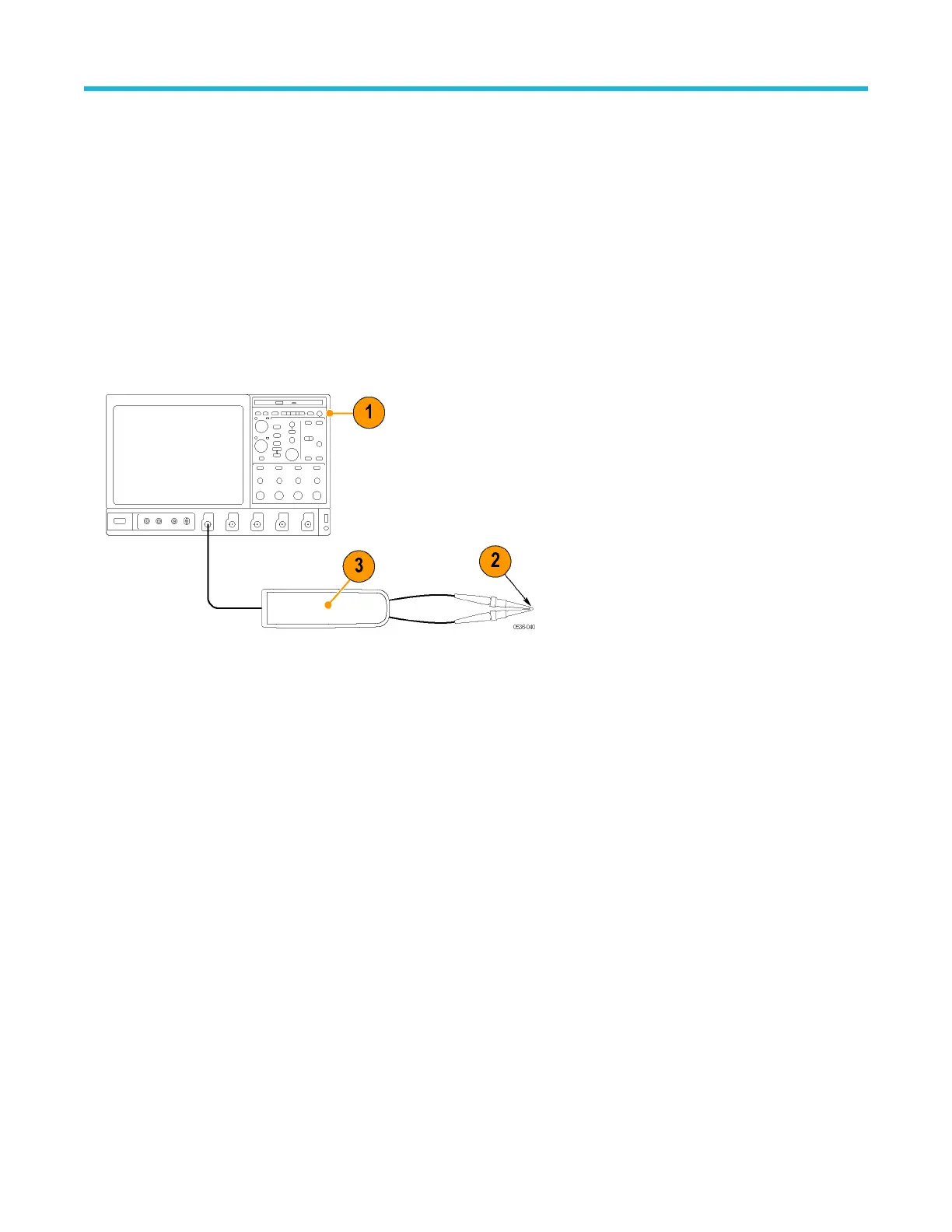
1. Set the oscilloscope offset to 0 volts.
2. Connect the probe inputs together with the hook tips.
3. Press and hold the probe BANDWIDTH LIMIT and RANGE buttons until the OVERRANGE LED on the probe flashes.
4. Release the buttons. The OVERRANGE LED continues to flash, indicating that the digitally-controlled of
fset zero adjustment is
enabled.
5. Use the probe BANDWIDTH LIMIT and RANGE buttons to set the probe offset voltage as close to 0 V as possible, as displayed on the
oscilloscope. The BANDWIDTH LIMIT button decreases the offset voltage and the RANGE button increases it.
6. Press the AUDIBLE OVERRANGE button on the probe to store the adjusted offset value. The OVERRANGE LED stops flashing to
indicate that the offset value is stored and that the adjustment is disabled.
7. Select the remaining attenuation range and repeat steps 3 on page 54 through 6 on page 54.
Adjustments
54

 Loading...


