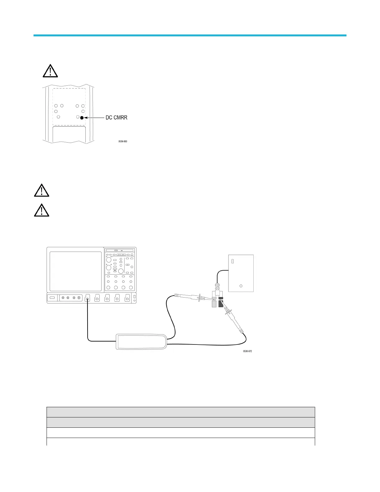
7. Using the narrow-bladed tool, adjust the DC CMRR pot in the probe to minimize the amplitude of the waveform displayed on the
oscilloscope. Use averaging or hi-res filters to make viewing the 40 Hz signal easier
.
WARNING: Use only an insulated tool to make the adjustment. Failure to do so presents a potential shock hazard.
8. Disable the generator output.
LF compensation
WARNING: Dangerous voltages will be present on the calibration generator output terminals and connection cables. Always verify
that the generator is in the standby mode before you make any connections to the generator
.
Note: The TMDP0200 probe only has one long-term +LF adjustment and one long-term –LF adjustment. The other two probe
models have two long-term +LF adjustments and two long-term –LF adjustments each.
1. Verify that the generator output is off.
2. Connect the probe inputs to the signal output connector on the back of the generator, using adapters if necessary. Connect the red
probe lead to the signal, and the black lead to ground.
3. Set the probe attenuation to the lower range for the probe that you are adjusting.
4. Set the oscilloscope horizontal to 4
μs/div, acq mode = average 16.
5. Set the generator fast-rise (rise time waveform) output frequency to 10 kHz.
6. Set the generator fast-rise output voltage to 50 V
p-p
.
Table 17: LF compensation test equipment settings
Probe Generator output
Model Range Voltage (p-p) Frequency
THDP0100 600 V 50 V 10 kHz
Table continued…
Adjustments
58

 Loading...


