Typical characteristics
T
ypical characteristics describe typical but not guaranteed performance.
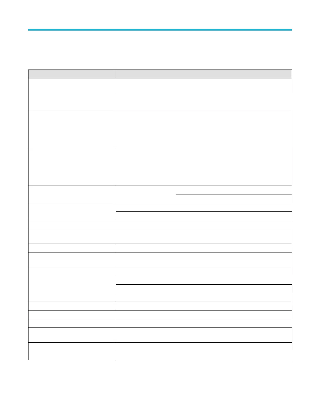
Table 6: Typical electrical characteristics
Characteristics THDP0100 THDP0200 TMDP0200
Maximum measurable differential voltage.
This is the maximum measurable range of
the probe. Beyond these limits, the output
could be clipped.
600 V Range: 600 V DC +
peak AC, 450 V
rms
150 V Range: 150 V DC +
peak AC, 100 V
rms
75 V Range: 75 V DC +
peak AC, 50 V
rms
6000 V Range: 6000 V DC +
peak AC, 3000 V
rms
1500 V Range: 1500 V DC +
peak AC, 1000 V
rms
750 V Range: 750 V DC +
peak AC, 500 V
rms
Maximum common mode voltage and input
voltage-to-earth. The Common Mode ratings
are the same as the input voltage-to-earth
ratings (the maximum amount that each
input lead (+/-) can be from ground).
±6000 V DC + peak AC,
2300 V CA
T I, 1000 V CAT
III
±1500 V DC + peak AC,
1000 V CAT II, 600 V CAT
III
±750 V DC + peak AC,
550 V CAT I, 300 V CAT III
CAT I Maximum Rated Over- Voltage
Transient (OVT). Applies to CAT I ratings
only (both ranges). The OVT peak is
typically measured on top of the Peak
Working Voltage.
4600 V
pk
NA 3220 V
pk
Bandwidth (-3 dB) DC to ≥100 MHz 150 V: DC to ≥160 MHz 75 V: DC to ≥160 MHz
1500 V: DC to ≥200 MHz 750 V: DC to ≥200 MHz
Offset zero (+20 °C to +30 °C) 600 V: ±1 V 150 V: ±500 mV 75 V: ±200 mV
6000 V: ±10 V 1500 V: ±5 V 750 V: ±2 V
Input resistance between inputs 40 MΩ ±2% 10 MΩ ±2% 5 MΩ ±2%
Input resistance between each input and
ground
20 MΩ ±2% 5 MΩ ±2% 2.5 MΩ ±2%
Input capacitance between inputs <2.5 pF <2.0 pF <2.0 pF
Input capacitance between each input and
ground
<5.0 pF per side <4.0 pF per side <4.0 pF per side
Common Mode Rejection Ratio (20–30°C) DC: >80 dB DC: >80 dB DC: >80 dB
100 kHz: >60 dB 100 kHz: >60 dB 100 kHz: >60 dB
3.2 MHz: >30 dB 3.2 MHz: >30 dB 3.2 MHz: >30 dB
100 MHz: >26 dB 100 MHz: >26 dB 100 MHz: >26 dB
Propagation delay 16 ns 14 ns 14 ns
DC offset drift (output referred) 50 μV/ °C 50 μV/ °C 50 μV/ °C
Bandwidth limit filters 5 MHz 5 MHz 5 MHz
Input overdrive recovery 600 V: <30 ns to 10% of final
value after 5X overdrive
150 V: <20 ns to 10% of final
value after 5X overdrive
75 V: <20 ns to 10% of final
value after 5X overdrive
Input referred noise (mV
rms
) 600 V: <175 mV 150 V: <50 mV 75 V: <25 mV
6000 V: <400 mV 1500 V: <140 mV 750 V: <65 mV
Specifications
40

 Loading...


