Rise time
1. V
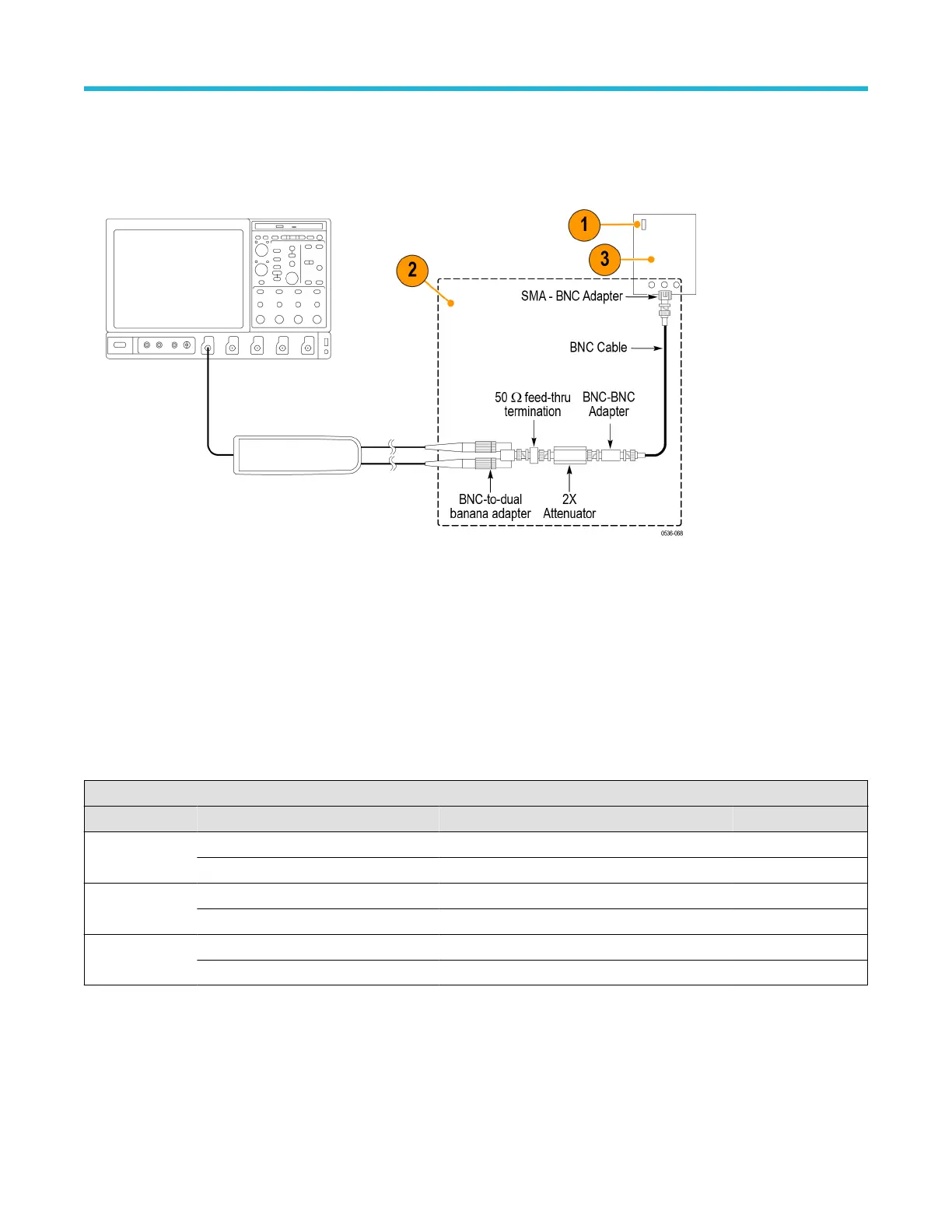
erify that the pulse generator output is off and then connect the probe to the oscilloscope.
2. Connect the probe inputs, through the adapters shown below, to the pulse generator output. Set the probe input leads straight and
parallel for best signal response.
3. Set the output of the pulse generator to 50 V
, 1 kHz, and a 200 ns pulse output. (The probe input voltage will be 25 V due to the 2X
attenuator in the circuit.)
4. Set the oscilloscope to 5 V/div, 10 ns/div, BW = full, average = 16.
5. Set the probe bandwidth to full and the attenuation to the first range listed in the table.
6. Enable the generator output and check that the rise time does not exceed the target rise time value listed in the table. Use the
auto-measure feature of the oscilloscope to determine the rise time.
7. Record the rise time in the test record.
8. Set the probe attenuation to the next range and adjust the vertical volts/div to display the signal.
9. Record the rise time in the test record and disable the generator output.
Table 11: Rise time test equipment settings
Probe Generator output Measurement
Model Range Voltage Frequency Target Measured
THDP0100 600 V 50 V 1 kHz ≤3.6 ns
6000 V 50 V 1 kHz ≤3.6 ns
THDP0200 150 V 50 V 1 kHz ≤2.4 ns
1500 V 50 V 1 kHz ≤2.0 ns
TMDP0200 75 V 50 V 1 kHz ≤2.4 ns
750 V 50 V 1 kHz ≤2.0 ns
Performance verification
High Voltage Differential Probes THDP0100/0200 and TMDP0200 User Manual 49
 Loading...


