Functional check
Using accessories that are shipped with your probe and a source that supplies AC line voltage, perform the following procedure:
WARNING: T
o reduce risk of shock or fire, ensure that the accessories are fully mated before you connect to voltage sources
above 42 Vpk.
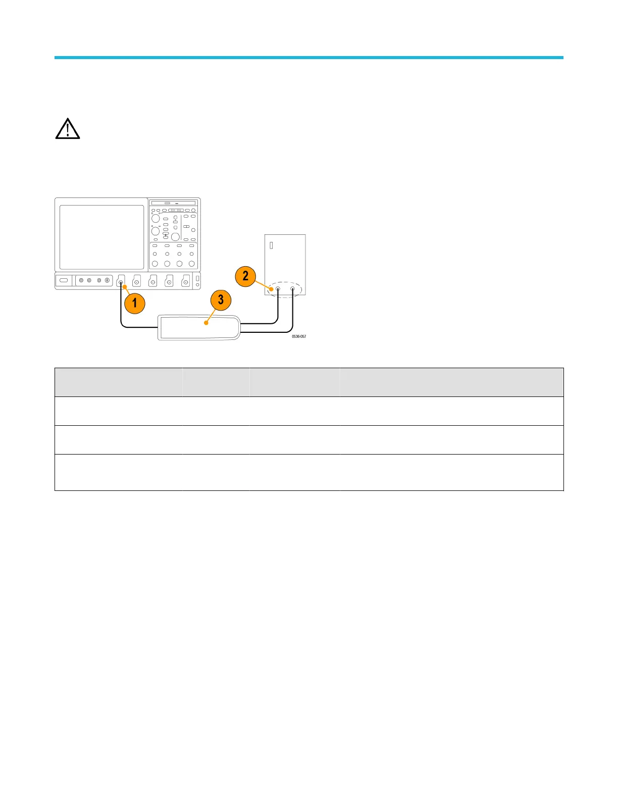
1. Connect the output of the probe to the oscilloscope input channel.
2. Connect the probe inputs to the AC voltage source.
3. Connect the inputs, set the voltage range, and perform the check as each row of the following table indicates.
Figure 4: Functional check setup
Input 1 (+ or
–)
Input 2 (– or +) Mode Range setting Check
Hot Ground or
Neutral
Differential High (6000 V, 1500 V,
or 750 V)
Measurement instrument displays or indicates the line
voltage
Hot Ground or
Neutral
Differential Low (600 V, 150 V, or
75 V)
Measurement instrument displays or indicates the line
voltage. Overrange indicator lights if the input is ~20% over
Hot Hot (same
connection)
Common Mode High or low
No signal. If a DC offset voltage is present, zero the DC
offset using the AutoZero function.
Probe operating information
High Voltage Differential Probes THDP0100/0200 and TMDP0200 User Manual 19

 Loading...


