Gain accuracy
The equipment settings for this test dif
fer between probes. Refer to the table for specific settings for the probe that you are testing. See
Table 15 on page 56.
WARNING: Dangerous voltages will be present on the calibration generator output terminals and connection cables. Always verify
that the generator is in the standby mode before you make any connections to the generator
.
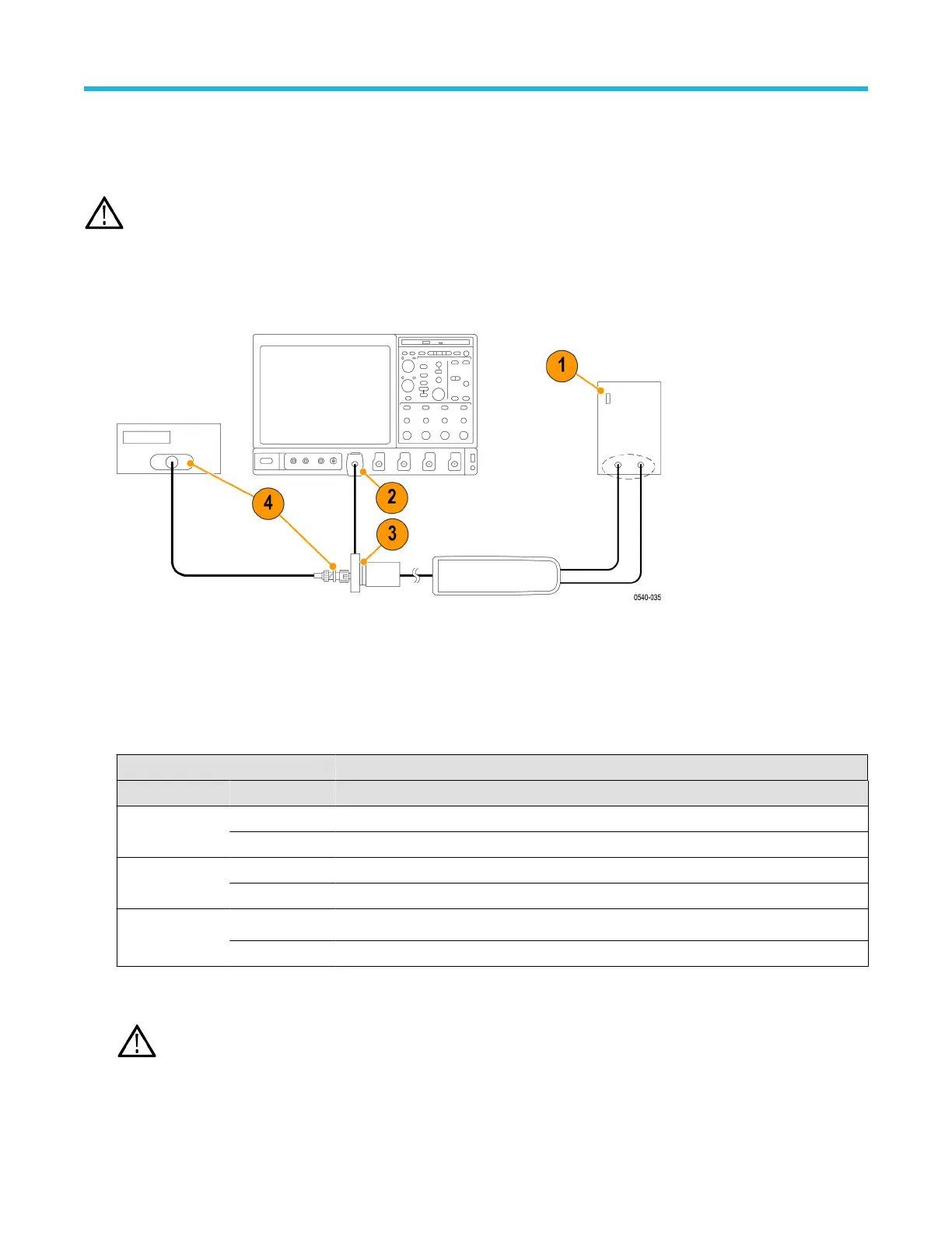
1. V
erify that the generator output is off.
2. Connect the probe calibration fixture to any channel (1–4) on the oscilloscope.
3. Connect the probe output to the probe calibration fixture.
4. Connect the output of the probe calibration fixture to the inputs of the DMM, using coax cables and adapters.
5. Set the DMM to AC volts.
6. Connect the probe inputs to the front outputs of the generator
, using adapters if necessary.
7. Set the probe attenuation to the lower (most sensitive) range for the probe that you are adjusting.
8. Set the generator square wave output frequency and RMS voltage (main display) to the values shown in the table for the probe that
you are adjusting. See Table 15 on page 56.
Table 15: Adjust gain accuracy equipment settings
Probe Generator square wave output Probe output voltage
Model Range Voltage (rms) Frequency Expected (rms) Measured (rms)
THDP0100 600 V 75 V 100 Hz 750 mV ±15 mV
6000 V 75 V 100 Hz 75 mV ±1.5 mV
THDP0200 150 V 25 V 100 Hz 500 mV ±10 mV
1500 V 75 V 100 Hz 150 mV ±3 mV
TMDP0200 75 V 20 V 100 Hz 800 mV ±16 mV
750 V 60 V 100 Hz 240 mV ±4.8 mV
9. Enable the generator output.
10. Adjust the low-range DC gain pot in the probe to
≤2% of the expected output.
WARNING: Use only an insulated tool to make the adjustment. Failure to do so presents a potential shock hazard.
Adjustments
56
 Loading...


