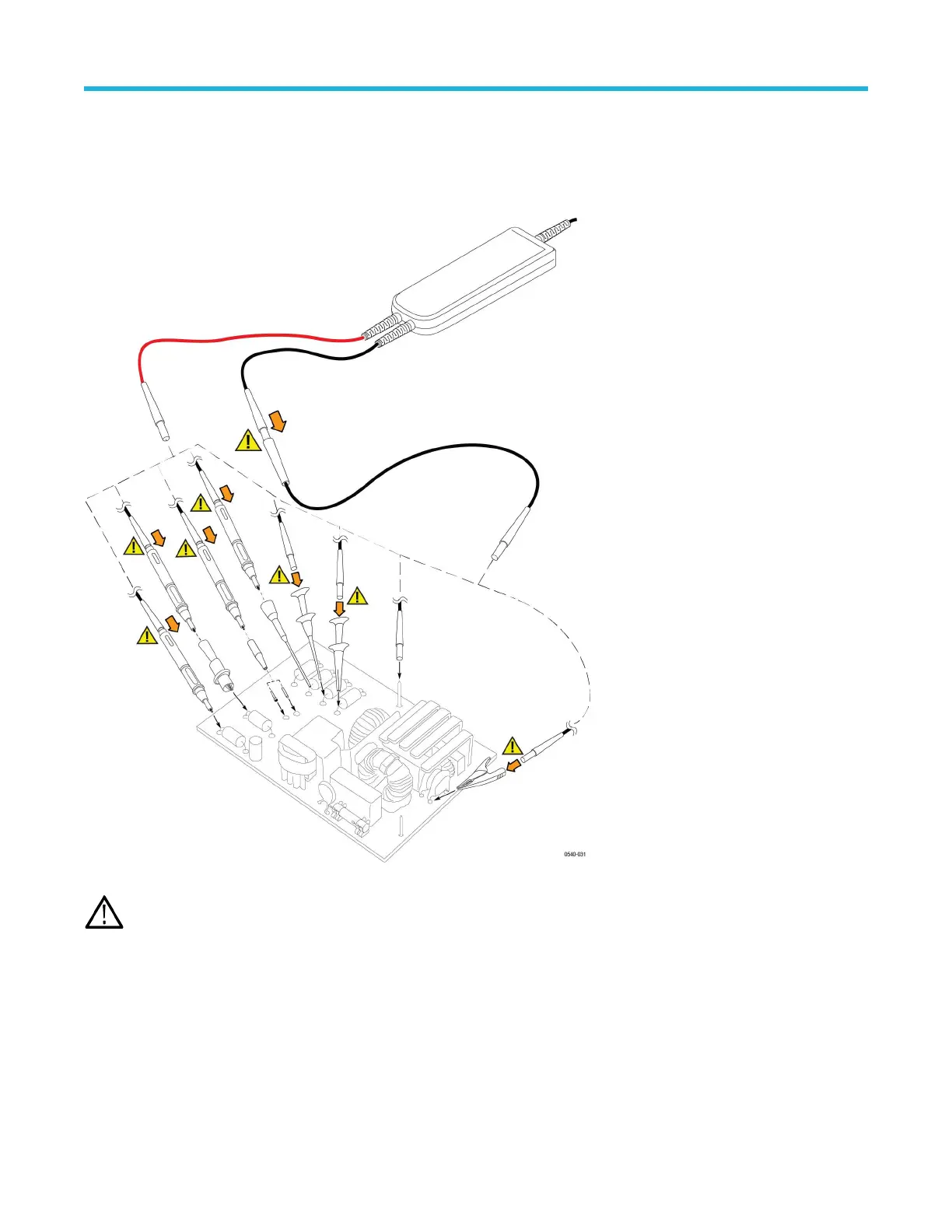
Connecting to the circuit
Make the connections to your circuit using the integral input leads or the accessories that best fit your application. The integral input leads
extend 10 in (25 cm) from the probe body
. Connect the leads directly to your circuit, or use the extender leads and the accessories that are
included with the probe.
WARNING: T
o avoid electrical shock or fire, always make the connections from the test leads to the probe accessory that you
intend to use before you make any connections to a voltage source. Always ensure that the connections between the test leads
and the probe accessories are secure before you connect them to a voltage source. Do not connect or disconnect accessories or
extended test leads to a voltage source unless they are first connected to the probe.
Probe controls and indicators
The probes have several features that make probing and measurement a simpler task. Familiarize yourself with the controls and indicators
shown on the following pages. Some features dif
fer from those illustrated, such as probe input voltage limit and voltage range, depending
on the probe model.
The probe release button, Status LED, and MENU buttons are located on the probe control box.
Probe operating information
High Voltage Differential Probes THDP0100/0200 and TMDP0200 User Manual 15

 Loading...


