11. Disable the generator output.
12. Set the probe attenuation to the next range and set the generator output voltage to the value shown in the table.
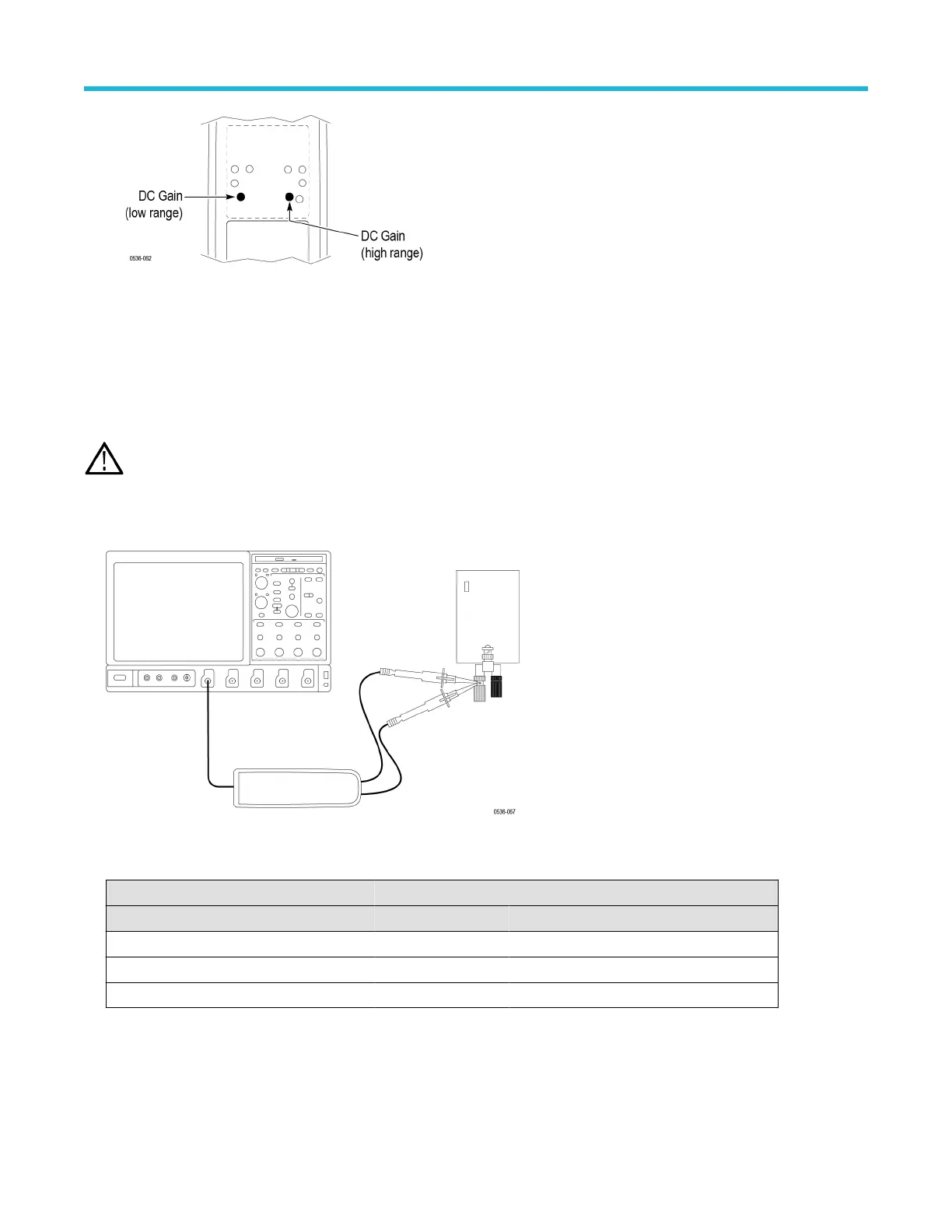
13. Enable the generator output and adjust the high-range DC gain pot in the probe to
≤2% of the expected output.
14. Disable the generator output.
DC CMRR
WARNING: Dangerous voltages will be present on the calibration generator output terminals and connection cables. Always verify
that the generator is in the standby mode before you make any connections to the generator
.
1. V
erify that the generator output is off.
2. Connect both of the probe inputs to the red (+) banana connector on the front output terminals of the generator. Use a BNC-banana
adapter if necessary.
3. Set the output of the generator to the voltage and frequency listed in the table.
Table 16: DC CMRR test equipment settings
Probe Generator output
Model Range Voltage (rms) Voltage (p-p) Frequency
THDP0100 600 V 353.53 V 1000 V 40 Hz
THDP0200 150 V 200 V 566 V 40 Hz
TMDP0200 75 V 353.53 V 1000 V 40 Hz
4. Set the oscilloscope horizontal to 10 ms/div and bandwidth to 5 MHz.
5. Set the probe attenuation to the lower (most sensitive) range of the probe.
6. Enable the generator output. Set the oscilloscope vertical to display the signal. For a stable display, connect the generator Sense
output to another channel and trigger off of that channel.
Adjustments
High Voltage Differential Probes THDP0100/0200 and TMDP0200 User Manual 57
 Loading...


