5-23
5
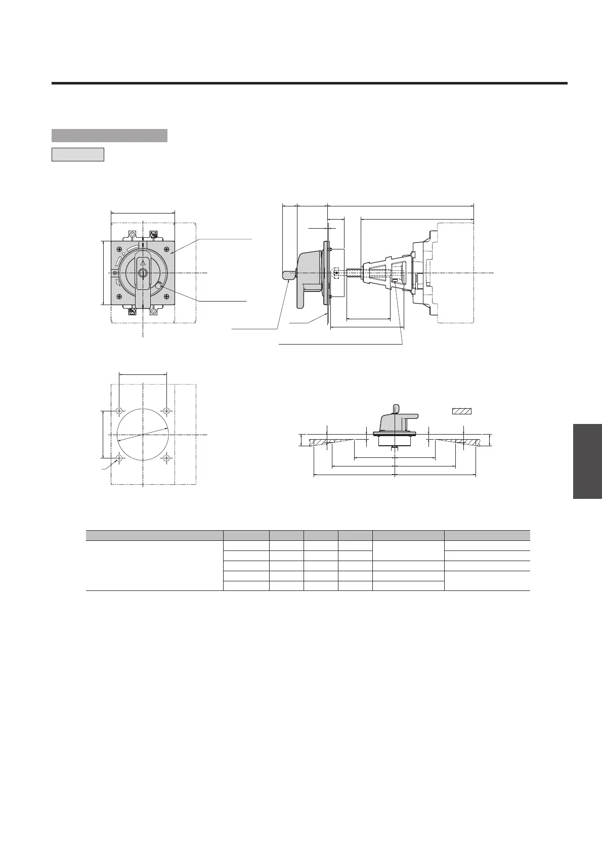
Accessories
Applicablebreakertypes A① B C D Squareshaftapplicable Shaftsupport
Note q:
“Min (minimum)” means the minimum possible distance from the panel surface to the breaker mounting surface, which can be formed by cutting the square shaft.
“Max (maximum)” means the maximum distance of the same section, which is formed with no cutting of the square shaft.
A: Distance from the panel surface to the breaker mounting surface
B: Length of the tube used to cover the square shaft
C: Length of the square shaft used
D: Distance from the tip of the shaft support to the breaker mounting surface
S250-SD, S250-GD, S250-SDN,
PVS160-SDL, PVS250-SDL,
PVS160-SNL, PVS250-SNL,
PVS160-SDH, PVS250-SDH,
PVS160-SNH, PVS250-SNH,
PVS160-GDH, PVS250-GDH
229 min.
56 107 186
T2PS251
Yes
243 max.
70 121 186
Yes
343 max.
170 221 186
T2PS252
Yes
443 max.
270 321 186
T2PS253
Yes
543 max.
370 421 186
T2PS254
H
L
C
L
D
A
31
1.2-3.2
C
5124
78
78
100
150
200
100
150
200
12
20
28
12
28
20
B
105
105
C
L
H
L
TRIP
ON
OFF
OPEN
RESET
4-ø10
ø85
Handle escutcheon
Panel lock release
Panel
M5 (Nominal size of Allen key applicable: 2.5)
• Positions of the hinge and handle as seen
from the load side of the breaker.
Ensure that the hinge is positioned
in the area.
Key for key lock
(optional)
¡Panel cutout dimensions
¡Outline dimensions
T2HP25L
H
L
: Handle Frame Centre Line
C
L
: Handle Centre Line
■ Outline dimensions
 Loading...