5-24
Externally mounted accessories
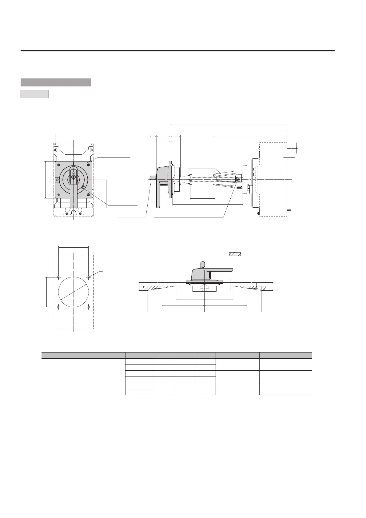
2. External operating handles
Applicablebreakertypes A① B C D Squareshaftapplicable Shaftsupport
Notes:
q. “Min (minimum)” means the minimum possible distance from the panel surface to the breaker mounting surface, which can be formed by cutting the square shaft.
“Max (maximum)” means the maximum distance of the same section, which is formed with no cutting of the square shaft.
w. When dimension A is in a range of 310 mm to 340 mm, cut square shaft T2PS402 to an appropriate length and use the shaft without shaft support.
A: Distance from the panel surface to the breaker mounting surface
B: Length of the tube used to cover the square shaft
C: Length of the square shaft used
D: Distance from the tip of the shaft support to the breaker mounting surface
S400-ND,
PVS400-NDL, PVS400-NNL,
PVS400-NDH, PVS400-NNH
270 min.
12
107.5
――
T2PS401
Non
310 max.②
52
147.5
――
410 max.
80
247.5
261
510 max.
180
347.5
261
T2PS403
610 max.
280
447.5
261
T2PS404
340 min.②
10
177.5
261
T2PS402
Yes
1.2-3.2
24
C
15
M6
D
B
A
51 34
L
H
C
L
105
105
100 100
150 150
200 200
12
12
20
28
20
28
L
C
130
130
100
C
L
H
L
4-ø10
ø
110
¡Panel cutout dimensions
¡Outline dimensions
Handle escutcheon
Panel lock release
Key for key lock
(optional)
M6 (Nominal size of Allen key applicable: 3)
• Positions of the hinge and handle as seen
from the load side of the breaker.
Ensure that the hinge is positioned
in the area.
Shaft support
T2HP40
ASL : Arrangement Standard Line
H
L
: Handle Frame Centre Line
C
L
: Handle Centre Line
■ Outline dimensions
 Loading...