5-26
Externally mounted accessories
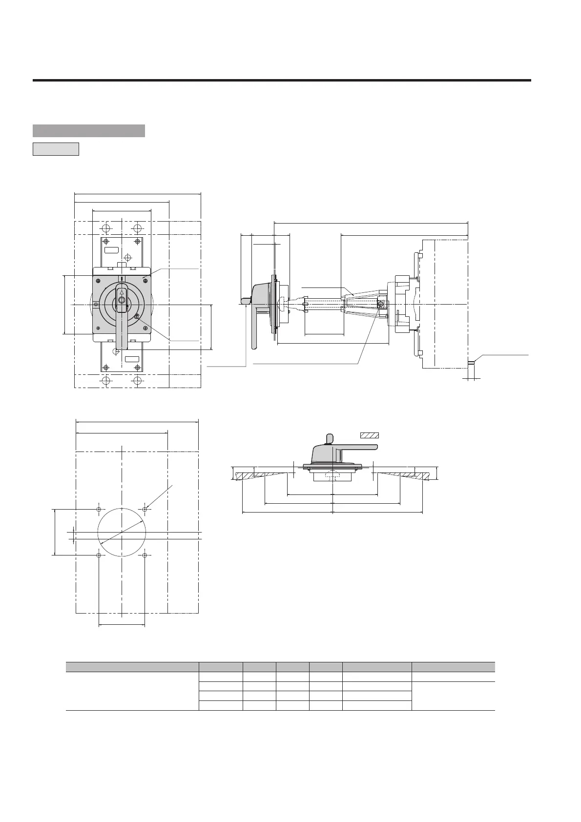
2. External operating handles
Applicablebreakertypes A① B C D Squareshaftapplicable Shaftsupport
XS1250ND, XS1600ND
387min.
52
147.5
337
T2PS401
Non
487max.
80
247.5
337
T2PS402
Yes
587max.
180
347.5
337
T2PS403
687max.
280
447.5
337
T2PS404
Note q:
“Min (minimum)” means the minimum possible distance from the panel surface to the breaker mounting surface, which can be formed by cutting the square shaft.
“Max (maximum)” means the maximum distance of the same section, which is formed with no cutting of the square shaft.
A: Distance from the panel surface to the breaker mounting surface B: Length of the tube used to cover the square shaft
C: Length of the square shaft used D: Distance from the tip of the shaft support to the breaker mounting surface
1.2-3.2
24
C
18
D
B
A
51 34
H
L
105
4P
3P
L
C
105
15
100 100
150 150
200 200
12
12
20
28
20
28
L
C
ASL
130
3P
4P
130
100
C
L
H
L
ø
110
Panel lock
release
Handle
escutcheon
¡Panel cutout dimensions
¡Outline dimensions
4-ø10
M6 (Nominal size of Allen key applicable: 3)
Key for key lock
(optional)
• Positions of the hinge and handle as seen
from the load side of the breaker.
Ensure that the hinge is positioned
in the area.
M8 mounting screw
Shaft support
T1HPX6
ASL : Arrangement Standard Line
H
L
: Handle Frame Centre Line
C
L
: Handle Centre Line
■ Outline dimensions
 Loading...