ACT6000 User Guide – January 2021 Page 44 of 52
- Power Spectral Density (with Spectrum Analyzer in High Impedance)
The PSD measurement, in Medium or High Band, can be performed in limited band by
the Spectrum Analyzer (not intrusive).
Set the instrument as follows:
- dBm or dBm/Hz by F1
- TX Off by F2
- 4W Bal by F3
- Normal or MaxVal by F4
- AC-Inp by F5
and then:
- Vo Rif for the best trace display
- dB/Div for the best vertical resolution
- Fc (kHz) for the Medium Band center
or RX Band (for one of the High Bands)
- kHz/Div for the Medium Band limit
- Zo RTX: Z-High
- Connect (in parallel) the line to a - b points of the RTX connector directly for unfed lines;
- Connect (in parallel) the line to a - b points of the RTX connector inserting the right Probe,
“ACT-15/6” (for medium Band) or “ACT-15/30” (for High Band), for fed lines and select
“Probe” by F5.
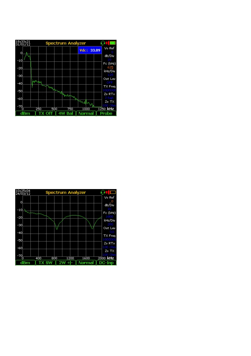
In the figure is shown the PSD measurement (subscriber side) of the typical ADSL stream
(over POTS), in fact the line feed is shown by the little “Vdc” window.
- Return Loss with Network Analyzer
The spectral measurement of the Return Loss in any band, can be performed in limited
band by the Network Analyzer. Set the Spectrum Analyzer as follows:
- dBm by F1
- TX SW by F2
- 2W +/- (or 2W Bal for High Band) by F3
- Normal by F4
- DC-Inp * by F5
and then:
- Vo Ref to 0
- dB/Div for the best vertical resolution
- Fc (kHz) for the Base / Medium Band
centre or RX Band (for one of the High
Bands)
- kHz/Div for the Medium Band limit
- Out Lev: 0.0 and Zo RTX: (eg. 100 Ohm)
Connect the line to a - b points of the RTX connector.
The setting made as in the example shown is used to measure the Return Loss of typical
copper pairs for the transport of ADSL2+ stream, where the bandwidth is from few kHz up
to 2 MHz (approx).
The typical value of the Return Loss of a good copper line (>1 km long ..at least) is
normally over 15 dB (see the table at the end of this paragraph).