ACT6000 User Guide – January 2021 Page 28 of 52
9. TDR Fault Locator
This item allows the selection of a useful function to locate a fault along the line or to
estimate its total length. Any impedance mismatches on the line under test are
shown as upward pulses when the impedance increases (up to the “open circuit”),
and downward pulses when the impedance decreases (up to the “short circuit”).
Measurement setup
From the Main Menu select and enter on the TDR Fault locator function.
- Connect the line under test to the a – b
point of the RTX connector and observe
the graph.
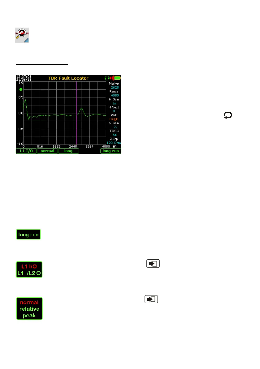
- If in the selected range a positive trace is
displayed (as shown on the image at
left) or negative (if the line was in short
circuit), select the “Marker” window by
key and arrows, then using the
arrows move the marker bar on “knee” of
last upward pulse; the distance is shown
in the marker window.
If necessary, optimize by using the ”Range” / “H Gain” / “H Sect” commands the horizontal
display of the trace in the center / right of the grid.
If necessary modify the “V Gain” parameter to optimize vertical display of the envelope,
and/or the “TDGC” parameter to increase or decrease the gain of the receiver.
The selection of the parameter related to the Pulse Velocity Factor (PVF, Ft/µs, V1/2 etc.)
and to the Distance Measure Unit (Meters or Feet) it must be performed into the “7.
Config. & Utility” menu.
To the automatic set of the PVF it is suggested to select the preponderant cable type from
the “8. Cable Setup” menu of the Config. & Utility” group (see at page 48).
To clean the trace related to a long and (over 3km) and very noisy line, it is
suggested to press the F5 “long run” key. A repetition of 64 tests (in about 20
seconds) will be able to clean the trace of the possible “end-of-line” echo.
Other setting:
By repeated pushing of the F1 key and “Enter” the IN/OUT of the TDR
front-end can be changed; the “L1 I/O” is the usual mode operation to localize
faults or anomalies on the line under test connected to RTX connector. The “L1
I/L2 O” is an useful operation mode to find and localize the possible cross-talk point (e.g.
due to split-pairs) between two lines connected to TX and RTX connector.
By repeated pushing of the F2 key and “Enter” the TDR operating mode
can be changed from “Normal” to “Relative” (to zero the echogram and
highlight only the new mismatching) or “Peak” to sample and hold intermittent
discontinuities during long term measurements.
The “Relative” mode is useful to detect mismatching among two lines on the same cable.
On this image is shown an echo-graph at the end of the monitoring time on “peak” mode.