ACT6000 User Guide – January 2021 Page 35 of 52
Insulation Test ATTENTION! Also for this test disconnect the external power supply!
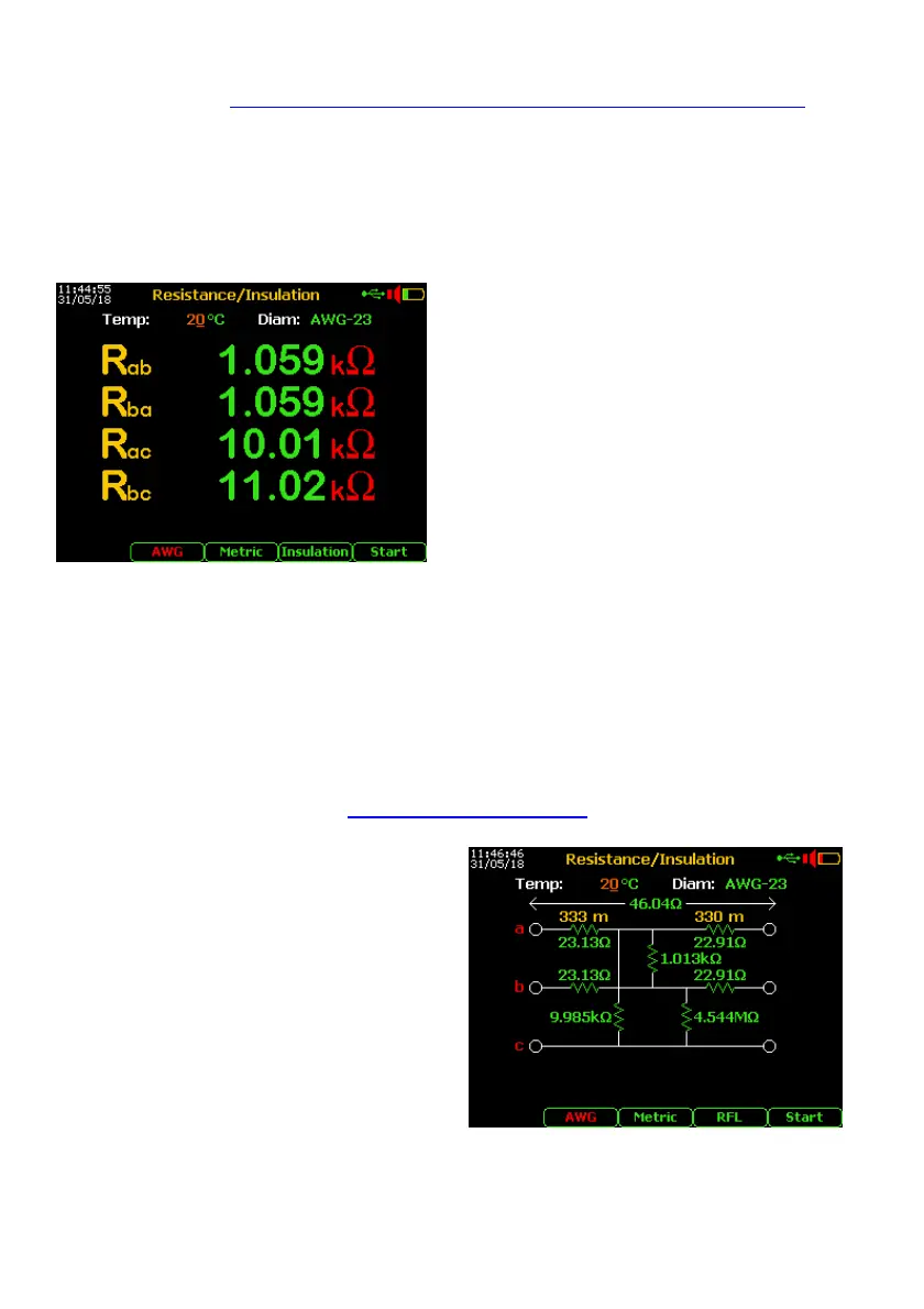
From the Main Menu select and enter the Digital Multimeter function, select item
3. Resistance/Insulation. By F4 select the “Insulation” test and push “Enter”.
Warning! During the test cycles don’t manage the line (a-b) or “ground” (c) connections.
Note: to the correct length estimation it is necessary to select the cable type from the Cable Setup
menu (see page 48) and, if possible, setting the right conductor resistivity (see 11.3).
- Connect the line to a – b points of the RTX
connector and the Gnd ref. to c point.
- By F3 set the presumed temperature of
the cable then press F5 “Start” *
If the result of insulation value between a,
b or c wires is under 20 MOhm, it is
possible to estimate the distance to the
fault by the RFL function.
* if found an extraneous voltage over 2.0 Volt,
the test will be blocked !
11.4. Low Insulation Localization (RFL) without extraneous voltage
First of all it is necessary to find the a or b conductor at the end of the line.
A possible method is to perform a short circuit between one conductor of the line and the
reference conductor (of other line or “earth” / “Gnd” reference point of the street cabinet,
box or the shielding of the cable).
Performing again the resistance measurement by pushing the F5 “Start” it is possible to
find what conductor (a or b) has been used for this test.
Remove the short-circuits and repeat the Insulation Test above described.
After the new Insulation Test, push more
time F4 to select “RFL” mode, then push
“Enter”.
Pushing F5 “Start” on the display will appear
the advises that invites the remote technician
to short some conductors.
Performed the first action it is necessary to
push again the F5 key and wait the possible
next steps following the instructions shown on
the display for the final calculation.