ACT6000 User Guide – January 2021 Page 46 of 52
- Insertion Loss meas. End-to-End manual or semi-automatic mode.
The Insertion Loss measurement (or line attenuation vs. frequency) can be performed with
a couple of instruments connected at the opposite ends of the line under test.
With the Generator & Meter function of two ACT6000 it is possible to perform this
measurement at a single frequency, by suitable setting of all the parameters (see the
Generator & Meter description and instructions).
Usually the Generator Output (a - b of the TX connector) must be connected to the remote
side of the line, and the Meter Input (a - b of the RTX connector) must be connected to the
local side of the line.
For the wide band spectral mode measurement (i.e. for PLCC line systems) it is necessary
to use the Spectrum Analyzer function as meter and the Step Generator as reference
signals.
Below the operation mode is described.
Meter setup
First of all it is necessary to define the
operating band by setting the Fc (Central
Frequency) and span by the kHz/Div.
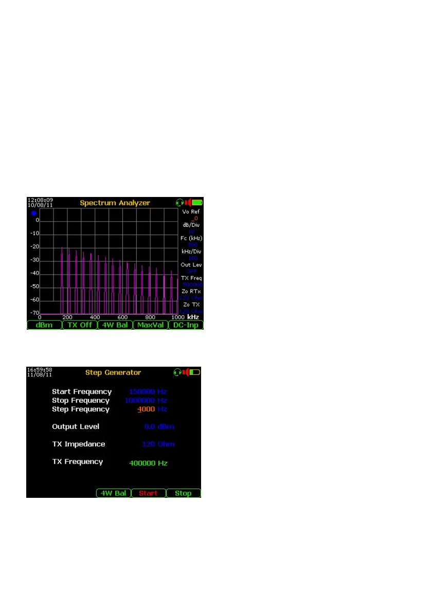
To hold the peak levels on the display it is
necessary to set the “Max Val” by the F4. To
do a quick test, useful to estimate the
attenuation vs. frequency (see the image at
the left), it is suggested to set the Step
Generator with “wide” steps (e.g. 4 kHz), in
this case the test time will take a few seconds.
To get a continuous trace it is necessary to set
the Step Generator with very small steps (e.g.
200 Hz) but the time test for the same band
will increased to over 15 minutes.
Step Generator setup
To perform the spectral Insertion Loss
measurement using the Spectrum Analyzer at
the opposite end of the line under test, set the
“Start Frequency” and “Stop Frequency” and
then set the “Step Frequency” (from 10 to
1000 Hz for Base Band and from 10 to 8000
Hz for the Medium Band).
Set the right “TX Impedance” (from 200 to 600
Ohm for Base Band and from 100 to 150 Ohm
for Medium Band) and if needed the Output
Level.
Press F4 “Start” to start the sweep, the frequency progress of the output signal is shown
(in green) in the “TX Frequency” field.
After the complete sequence (from Frequency Start to Frequency Stop), press F5 “Stop” to
finish the test.