ACT6000 User Guide – January 2021 Page 38 of 52
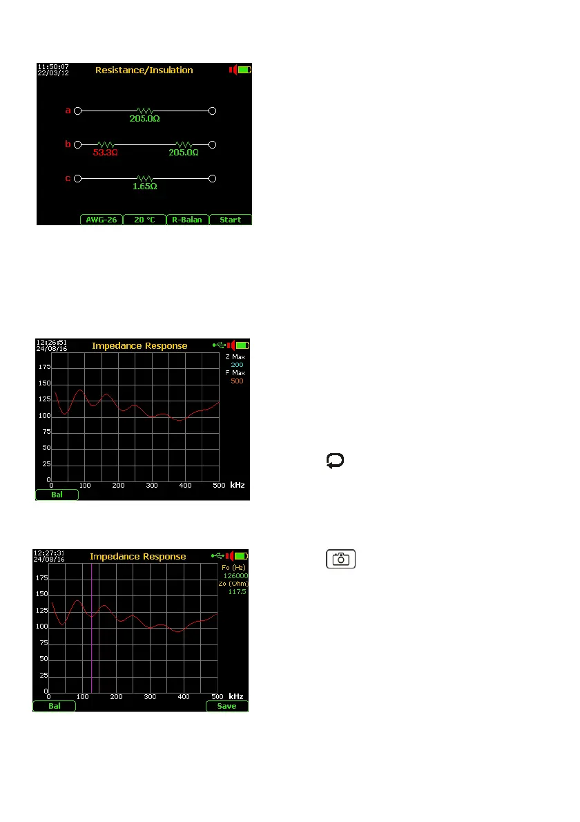
11.6. Resistive Balancement “R-bal” measurement
From the Main Menu select and enter the Digital
Multimeter function, select item “3. Res. /
Insulation“
By the F4 select the R Balan” function, then press
“Enter”. Connect the wires of the line under test
and the reference wire (or “Gnd” reference) to the
a - b and c points respectively of the RTX
connector.
Pushing the F5 “Start” * will appear the advise
that invites the remote technician to short the
three conductors at the other side of the line.
Push again the F5 “Start” key and wait the end of
the test. If the resistance value of the a it is different over 5 Ohm respect to the b wire, will
be shown on graph the additional (differential) resistor and its resistance value (in red) as
the figure above.
* if found an extraneous voltage over 2.0 Volt, the test will be blocked !
11.7. Line / Load Impedance Response
From the Main Menu select and enter the Digital
Multimeter function, then select the item “5.
Impedance Response”.
Connect the wires of the balanced line (or load
under test) to the a - b of the RTX connector, or
unbalanced line (or load) using the Banana to BNC
Adapter (option ALT-16) *.
Pushing the key and arrows select the “Z
Max” (maximum impedance range) and “F Max”
(maximum frequency range).
*To perform the measurement on unbalanced line/load press F1 key to select “Unb” mode.
The display will shows the impedance response up to the maximum frequency set.
Pushing the “Photo” key, the measurement
can be frozen and will be enabled the marker.
Moving the marker using the arrows will be
possible to read the exact impedance value for any
specific frequency.
Besides pushing the F5 key is allowed the saving
on the measurement in the internal memory.