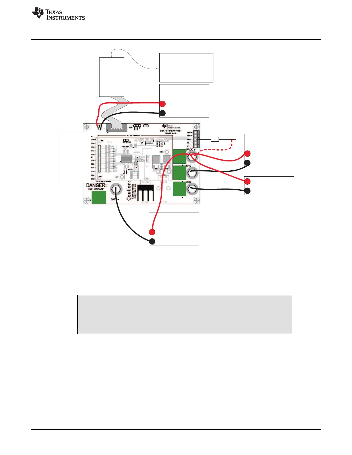
“Charger”
supply
+
-
Resistor
Cell
Simulator
USB
Interface
Adapter
PC
“Battery”
supply
+
-
USB
~ 15k ohm
“Programming”
supply
(14V)
+
-
Load+
-
www.ti.com
Software Operation
Figure 3. EVM Connection for Communication and Programming
To connect the computer to the GUI and start the software use the following steps:
1. Connect the TI USB interface adapter to the computer.
2. Connect the 10 pin connector from the interface adapter to the EVM J3.
CAUTION
The communication interface is not isolated on the EVM. Be sure no ground
potential exists between the computer and the EVM. Also be aware that the
computer will be referenced to the Battery- potential of the EVM.
3. Remove any shunt installed on J6 so the interface can control ZEDE.
4. Connect the "battery" power supply to the EVM, adjust to approximately 30 to 40VDC.
5. Wake the bq77910A by connecting CHGCTL high.
6. Start the software, typically using Start > All Programs > Texas Instruments > bq77908-bq77910
Evaluation.
When started, the software will look for the communication interface and the device. When communication
is established with the device, the main window appears as shown in Figure 4.
11
SLUU855–February 2012 bq77910AEVM
Submit Documentation Feedback
Copyright © 2012, Texas Instruments Incorporated