bq77910A Circuit Module Physical Construction
www.ti.com
8.1.3 bq77910A Circuit Module Performance Specification Summary
This section summarizes the performance specifications of the bq77910A circuit module in its default 10-
cell parallel FET configuration.
Typical voltage will depend on the number of cells configured. Typical current will depend on the
application. Board cooling may be required for continuous operation at or below maximum current.
Table 11. Performance Specification Summary
Specification Min Typ Max Unit
Input voltage PACK+ with respect to BATT–, CHG–, or DSG– 5.6 – 43 V
Continuous discharge current (current into DSG– terminal) 0 – 30 A
Continuous charge current (current into CHG– terminal) 0 - -6 A
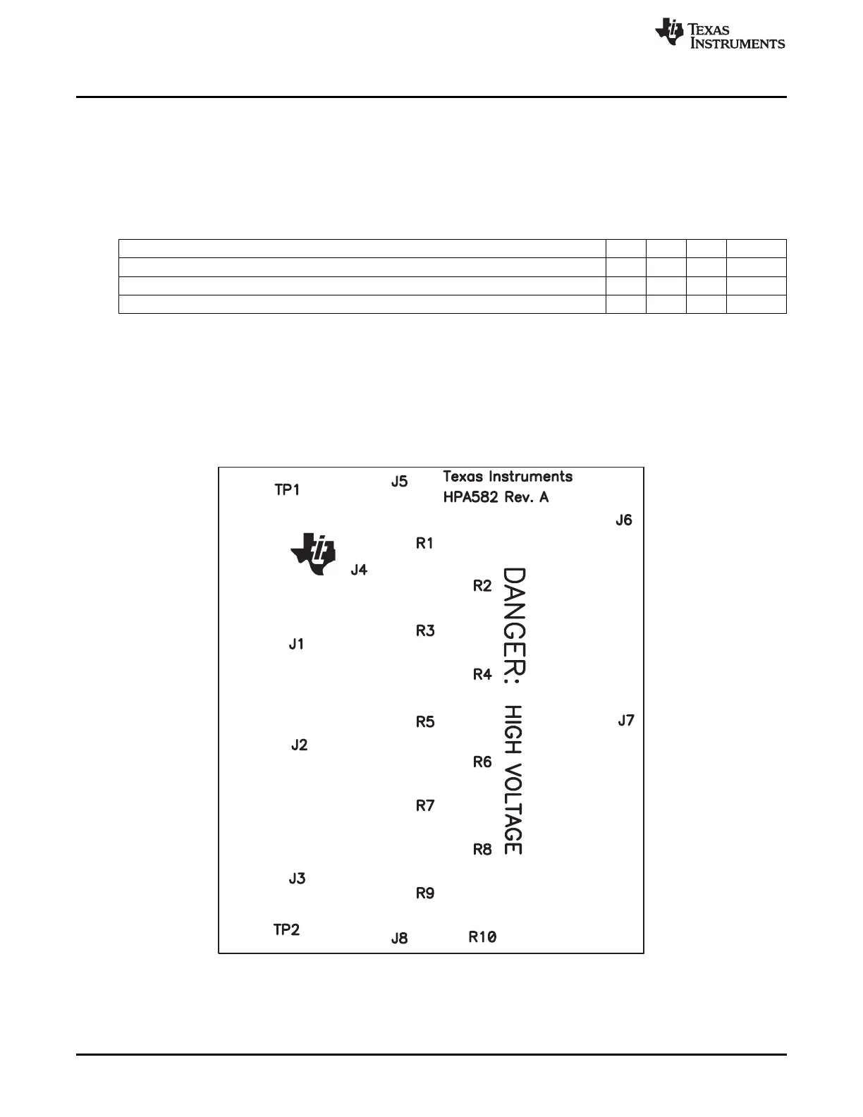
8.2 Resistor Cell Simulator
8.2.1 Board Layout
The resistor cell simulator is a 1.75-inch x 2.00-inch 2-layer circuit card assembly. It is designed for easy
connection to the bq77910A circuit card assembly using the connectors on the bottom side. Additional
patterns are included on the board for test points.
Figure 20. Resistor Simulator Top Silkscreen
32
bq77910AEVM SLUU855–February 2012
Submit Documentation Feedback
Copyright © 2012, Texas Instruments Incorporated