bq77910A EVM Hardware Connection and Operation
www.ti.com
A communication interface is not required for basic operation, and it should be connected to the computer
and EVM circuit module only after proper installation of software. The software along with an appropriate
communication interface allows setting the programmable safety limits of the device and checking the
status after fault detection. Installation of the software and its use are described in a later section.
3.2 Connecting the Cell Simulator
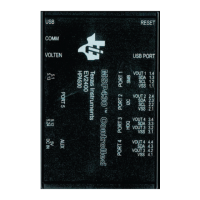
The cell simulator consists of headers to mate the board and ten (10) 200-Ω resistors to divide the battery
voltage between the inputs. Power is provided through the Cell0 and Cell10 connections on the terminal
block headers. Various test points are provided on the board. Refer to physical construction section for
additional details.
• Be certain no power is applied to the board.
• Unplug the screw terminal blocks from J4 and J5 of the EVM and save these for later use.
• Plug the cell simulator board onto J4 and J5. Support may be required on the bottom of the EVM while
the connectors are pressed together firmly.
CAUTION
Do not connect or remove the cell simulator board while power is applied to the
EVM. The resistor pull down or up from intermittent connections will overstress
the device inputs.
3.3 Simulated Battery Connection
Connect a power supply between BATT– (negative) and PACK+ (positive). This power supply will connect
to the resistor cell simulator through default connections on the bq77910A circuit module.
3.4 Pack Connections
A load or charger is connected to the pack terminals using the terminal blocks provided. It is
recommended that the load or charger be connected with the current switched off to prevent arcing or
transients during connection of the wires to the terminal blocks. Charger detection is required for the
bq77910A with a signal at the CHGST pin. Charger detection can be provided by connecting a resistor
from the CHGCTL terminal of the board to the PACK supply, or with a logic level voltage supply for
evaluation. An external resistor is required due to the low resistance pull down on the board. The selected
resistor should keep the CHGST voltage above the VCHG_DET1 data sheet threshold over the entire
evaluation voltage range while limiting the power in the 1k-Ω pulldown resistor to 1/16W or less. A 15k-Ω
1/4W resistor is typically suitable for the default configuration, a smaller value may be required for low
voltage or if the configuration is changed.
WARNING
The CHGCTL should not be tied to the power supply without the
external resistor since the 1k resistor on the board will become
very hot and may damage the board.
Although designed for 30A operation, the board may not dissipate enough power to operate without
exceeding all component ratings. The user should monitor the temperature of the board and components
during evaluation and provide cooling air and/or heatsinks as required for operation. The thermal sensor
on the board may not respond to protect the FETs from damaging temperatures due to its location and
possible thermal gradients on the board.
6
bq77910AEVM SLUU855–February 2012
Submit Documentation Feedback
Copyright © 2012, Texas Instruments Incorporated
 Loading...


