www.ti.com
bq77910A Circuit Module Physical Construction
Q1, Q2 and related components provide a switch for the 14V programming voltage controlled by the
interface adapter. It is expected this circuitry would be on a production fixture in a system design. R24
provides a pulldown for the EEPROM pin when programming voltage is not present, this resistor can be
smaller to avoid noise depending on the capability of the programming power supply and switch. When
programming the EVM with software other than the bq77908-10-GUI-SW Evaluation Software and
supported host interface, provide a logic control to the J3 PGM pin at the appropriate time indicated in the
data sheet programming diagram.
8 bq77910A Circuit Module Physical Construction
This section contains the PCB layout, bill of materials and schematic of the bq77910AEVM circuit module.
The bq77PL910AEVM-001 consists of two circuit module assemblies, the bq77PL910AEVM main board or
HPA462, and the resistor simulator or HPA582.
8.1 Main Board
8.1.1 Board Layout
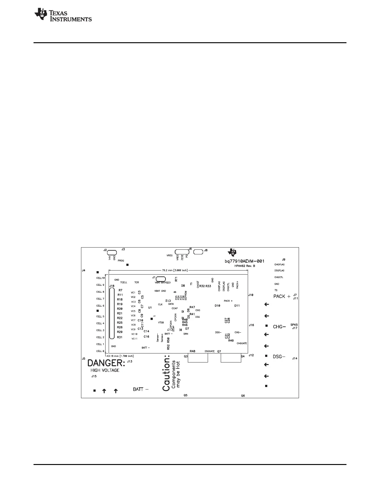
The bq77910AEVM circuit module is a 4.5-inch × 3.25-inch 2-layer circuit card assembly. It is designed for
easy connection with cell connections on the left side and load connection on the right using standard
wires to the terminal blocks. The board was planned for 30A current flow. Wide trace areas are used to
reduce voltage drops. The EVM layout and construction allows easy understanding of the connections for
evaluation, but the connector area and programming features result in a large board. The main solution
components are outlined on the silkscreen layer, the discharge FET can be envisioned moving into this
area, and area might further be reduced by careful layout.
See additional information in the configuration and operation sections of this document. Figure 10 to
Figure 17 show the board layout.
Figure 10. Top Silkscreen
23
SLUU855–February 2012 bq77910AEVM
Submit Documentation Feedback
Copyright © 2012, Texas Instruments Incorporated