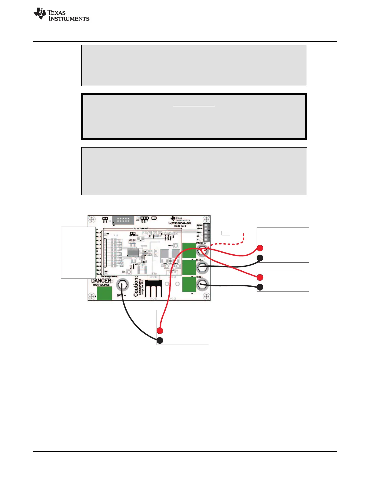
“Charger”
supply
+
-
Resistor
Cell
Simulator
“Battery”
supply
+
-
~ 15k ohm
Load+
-
www.ti.com
bq77910A EVM Hardware Connection and Operation
CAUTION
The bq77910A circuit module may be damaged by over temperature. To avoid
damage, monitor the temperature during evaluation and provide cooling as
needed for your system environment.
WARNING
The bq77910A circuit module may become hot during operation
due to dissipation of heat. Avoid contact with the board. Follow all
applicable safety procedures applicable to your laboratory.
CAUTION
Some power supplies can be damaged by application of external voltages. If
using more than 1 power supply check your equipment requirements and use
blocking diodes or other isolation techniques as needed to prevent damage to
your equipment.
The connection of the EVM will look similar to Figure 1.
Figure 1. Basic EVM Setup
3.5 Basic Operation
The following steps are suggested for basic operation of a default EVM with the cell simulator and the
default configuration in EEPROM.
1. Confirm the cell simulator board is installed on the EVM.
2. Connect a power supply between the BATT– (negative) and PACK+ (positive) terminals.
3. Connect a 15k-Ω 1/4W resistor to the CHGCTL terminal of the board.
4. Set the bench supply to approximately 36V.
5. Connect a disabled load between the DSG– (negative) and PACK+ (positive) terminals.
7
SLUU855–February 2012 bq77910AEVM
Submit Documentation Feedback
Copyright © 2012, Texas Instruments Incorporated