bq77910A EVM Circuit Description and Configuration
www.ti.com
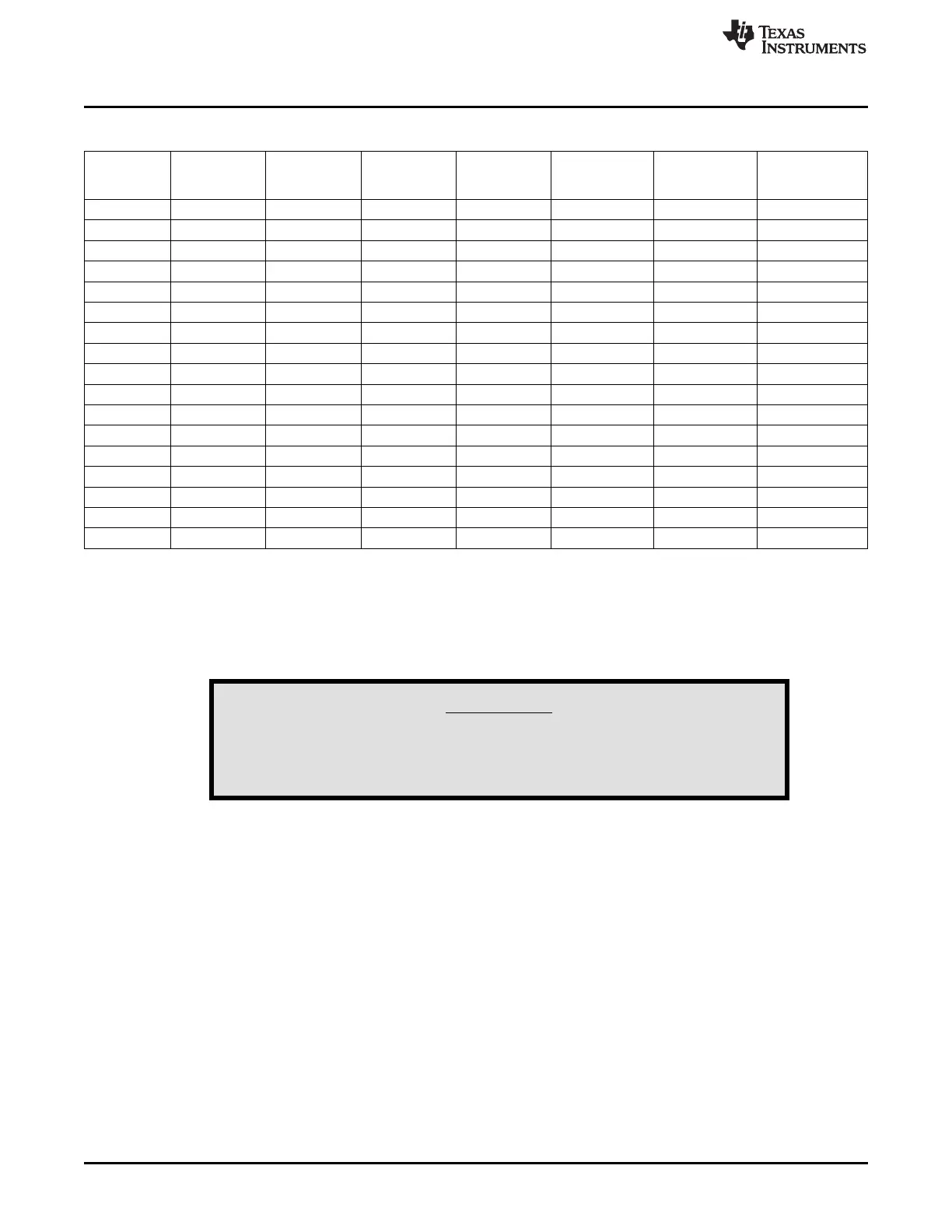
Table 9. Cell Count Component Configuration (continued)
Cell Count/
10 Cells
Reference 9 Cells 8 Cells 7 Cells 6 Cells 5 Cells 4 Cells
(Default)
Designator
R18 installed installed installed Remove Remove Remove Remove
R19 installed installed installed installed Remove Remove Remove
R20 installed installed installed installed installed Remove Remove
R21 installed installed installed installed installed installed Remove
R53 — — — — — — 0 Ω
R54 — — — — — 0 Ω —
R55 — — — — 0 Ω — —
R56 — — — 0 Ω — — —
R57 — — 0 Ω — — — —
R58 — 0 Ω — — — — —
R59 installed Remove Remove Remove Remove Remove Remove
R60 — 100 Ω 0 Ω 0 Ω 0 Ω 0 Ω 0 Ω
R61 — — 100 Ω 0 Ω 0 Ω 0 Ω 0 Ω
R62 — — — 100 Ω 0 Ω 0 Ω 0 Ω
R63 — — — — 100 Ω 0 Ω 0 Ω
R64 — — — — — 100 Ω 0 Ω
R65 — — — — — — 100 Ω
The cell count programmed in the EEPROM must match the physical connection for proper operation. If
the device is programmed for more than the connected cells, the unused cells will still be checked by the
device and will show undervoltage or open cell faults. If the device is programmed for fewer than the
connected cells, the upper cells are ignored and faults on these cells are not checked. Also be aware of
the voltage applied to the part could exceed the absolute maximum or show undervoltage when used with
the resistor simulator.
WARNING
When the device is configured for fewer than the connected cells
the device does not monitor the upper cells and will not protect
against faults on those un-monitored cells.
7.4 Ground Connection
The IC VSS (ground) reference on the bq77910AEVM-001 circuit module is connected to the BATT– at
the sense resistor. Note the range of the inputs when considering moving the ground location in an
application design. The ground connection should be made at one location on the high current path to
avoid differential voltages on the board ground due to high currents.
7.5 Current Sense Connections
R50 and R52 in parallel make the current sense resistor. Two resistors allow for lower heat dissipation per
component at a given current, and allow flexibility in evaluation. R43 and R44 isolate the sense input pins
from the current path transients, C20 and C25 provide filtering. Be aware that C20 and C25 will add a time
delay to the system current response depending on where sense resistor voltage falls in relation to the
threshold voltage. A mismatch in C20 and C25 can convert a common mode signal to a differential signal
at the device pins, the C22 pattern is available if a differential filter is desired.
20
bq77910AEVM SLUU855–February 2012
Submit Documentation Feedback
Copyright © 2012, Texas Instruments Incorporated